

Question: Problem 1. Consider the RLC circuit shown below. The circuit components have the values & = 5 V, R1 = 1 0, R2 = 0.1
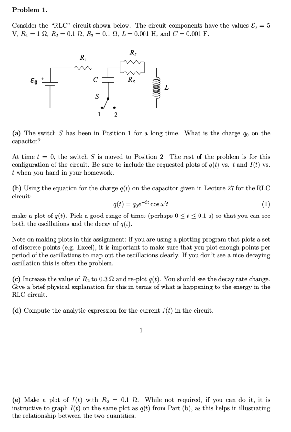
Problem 1. Consider the "RLC" circuit shown below. The circuit components have the values & = 5 V, R1 = 1 0, R2 = 0.1 0, R: = 0.1 0, L = 0.001 H, and C = 0.001 F. R R2 Eo R3 L S (a) The switch S has been in Position 1 for a long time. What is the charge go on the capacitor? At time t = 0, the switch S is moved to Position 2. The rest of the problem is for this configuration of the circuit. Be sure to include the requested plots of q(t) vs. t and I(t) vs. t when you hand in your homework. (b) Using the equation for the charge q(t) on the capacitor given in Lecture 27 for the RLC circuit: q (t) = que-Be cosw't (1) make a plot of q(t). Pick a good range of times (perhaps (
Step by Step Solution
There are 3 Steps involved in it

Get step-by-step solutions from verified subject matter experts