

Question: Consider the RLC circuit shown below. The circuit components have the values E = 5 V, R = 1, R2 = 0.1 N, R3
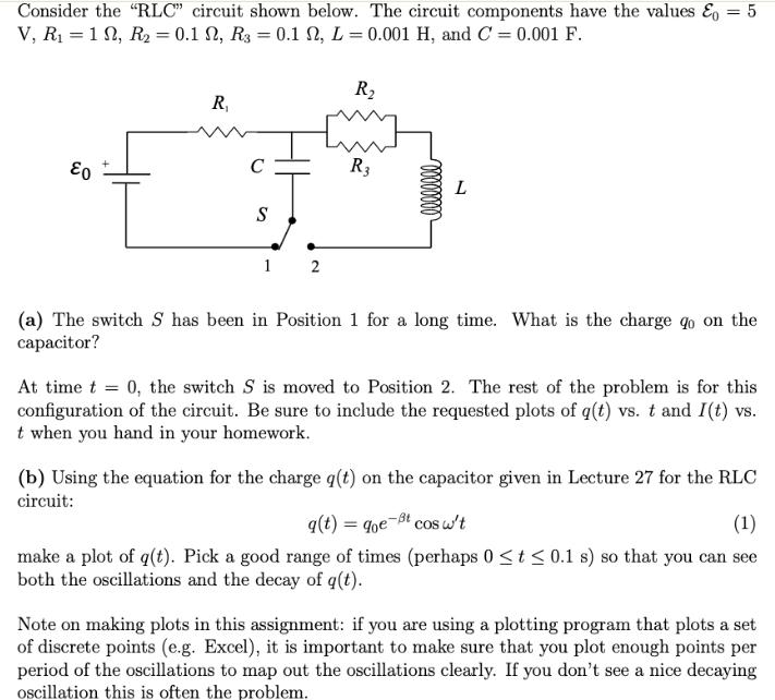
Consider the "RLC" circuit shown below. The circuit components have the values E = 5 V, R = 1, R2 = 0.1 N, R3 = 0.1 N, L = 0.001 H, and C = 0.001 F. E0 R R C R3 S 1 2 llllllll L (a) The switch S has been in Position 1 for a long time. What is the charge go on the capacitor? At time t = 0, the switch S is moved to Position 2. The rest of the problem is for this configuration of the circuit. Be sure to include the requested plots of q(t) vs. t and I(t) vs. t when you hand in your homework. g(t) = qoe -t cos w't (b) Using the equation for the charge q(t) on the capacitor given in Lecture 27 for the RLC circuit: (1) make a plot of q(t). Pick a good range of times (perhaps 0 (c) Increase the value of R2 to 0.3 2 and re-plot q(t). You should see the decay rate change. Give a brief physical explanation for this in terms of what is happening to the energy in the RLC circuit. (d) Compute the analytic expression for the current I(t) in the circuit. 1 (e) Make a plot of I(t) with R2 = 0.1 2. While not required, if you can do it, it is instructive to graph I(t) on the same plot as q(t) from Part (b), as this helps in illustrating the relationship between the two quantities.
Step by Step Solution
There are 3 Steps involved in it

Get step-by-step solutions from verified subject matter experts