

Question: Problem 1: Initially, the switch in Fig 1. is in its position A and Switch capacitors C and C, are uncharged. Then the switch is
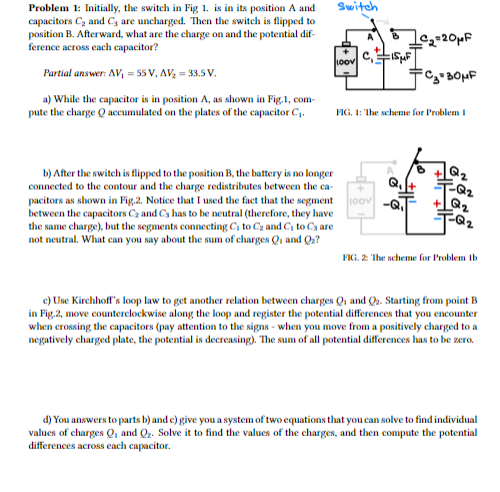
Problem 1: Initially, the switch in Fig 1. is in its position A and Switch capacitors C and C, are uncharged. Then the switch is flipped to position B. Afterward, what are the charge on and the potential dif- B C,=20 MF ference across each capacitor? Partial answer AV, = 55 V, AV, = 33.5 V. a) While the capacitor is in position A, as shown in Fig.1, com- pute the charge O accumulated on the plates of the capacitor C. FIG, 1: The scheme for Problem I b) After the switch is flipped to the position B, the battery is no longer B Q 2 connected to the contour and the charge redistributes between the ca- -T-Q2 pacitors as shown in Fig.2. Notice that I used the fact that the segment -Q. + Q 2 between the capacitors Ca and Cs has to be neutral (therefore, they have the same charge), but the segments connecting C to C and Ci to Cs are -T-Q 2 not neutral. What can you say about the sum of charges Q, and Qa? FKi. 2 The scheme for Problem ib c) Use Kirchhoff's loop law to get another relation between charges Qi and Qa. Starting from point B in Fig.2, move counterclockwise along the loop and register the potential differences that you encounter when crossing the capacitors (pay attention to the signs - when you move from a positively charged to a negatively charged plate, the potential is decreasing). The sum of all potential differences has to be zero. d) You answers to parts b) and c) give you a system of two equations that you can solve to find individual values of charges Q, and Q2. Solve it to find the values of the charges, and then compute the potential differences across each capacitor
Step by Step Solution
There are 3 Steps involved in it

Get step-by-step solutions from verified subject matter experts