

Question: Problem 1 Use the same loading ( i . e . shear / moment diagram ) as Problem 1 from ( mathrm {
Problem
Use the same loading ie shearmoment diagram as Problem from mathrmHW# see solution for the correct shearmoment diagram as well as the following given information: The crosssection height is prime prime and the width is prime prime and the concrete is normalweight concrete and f mathrmksi The longitudinal reinforcement are # bars and all bars are mathrmFmathrmymathrmksi Use the appropriate cover for the beam not exposed to earth in order to determine d
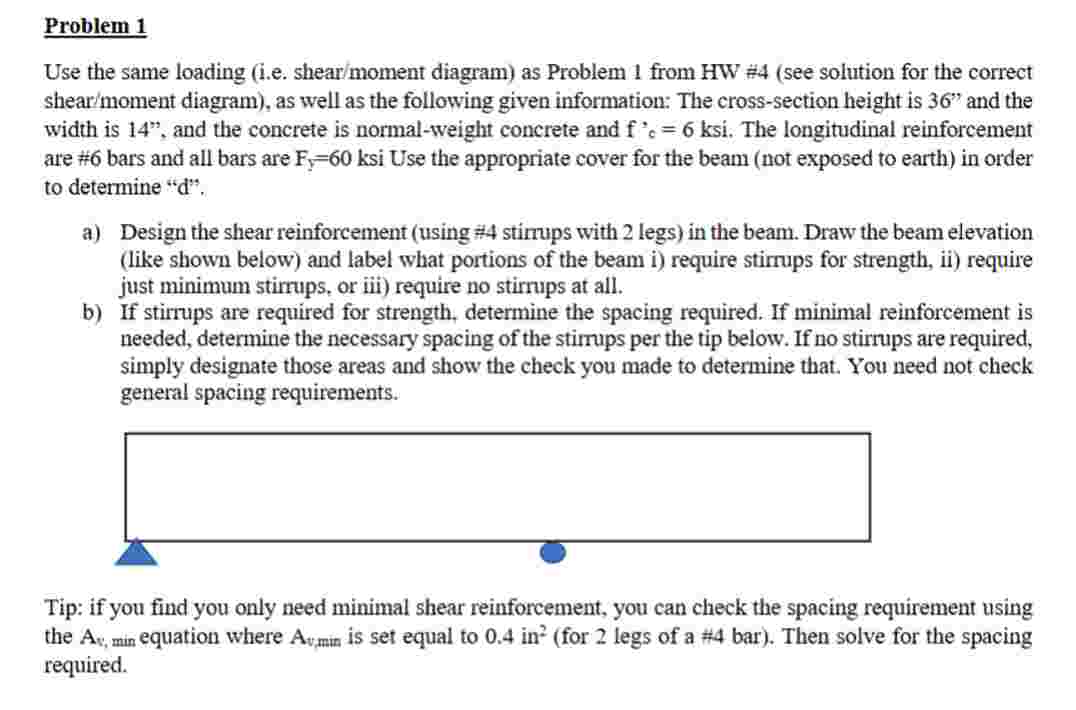
a Design the shear reinforcement using # stimps with legs in the beam. Draw the beam elevation like shown below and label what portions of the beam i require stirrups for strength, ii require just minimum stirrups, or iii require no stirrups at all.
b If stirrups are required for strength, determine the spacing required. If minimal reinforcement is needed, determine the necessary spacing of the stirrups per the tip below. If no stirrups are required, simply designate those areas and show the check you made to determine that. You need not check general spacing requirements.
Tip: if you find you only need minimal shear reinforcement, you can check the spacing requirement using the mathrmAvtext min equation where mathrmAvmin is set equal to mathrminfor legs of a # mathrmbar Then solve for the spacing required.
Step by Step Solution
There are 3 Steps involved in it
1 Expert Approved Answer
Step: 1 Unlock

Question Has Been Solved by an Expert!
Get step-by-step solutions from verified subject matter experts
Step: 2 Unlock
Step: 3 Unlock