

Question: Problem 14: Approach to Steady State (a) Figure 10.22 shows the steady-state position (left) and velocity (right) versus time for a driven, damped, harmonic
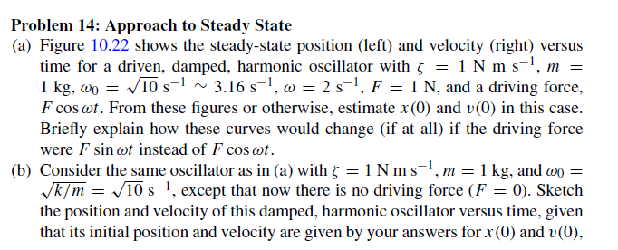
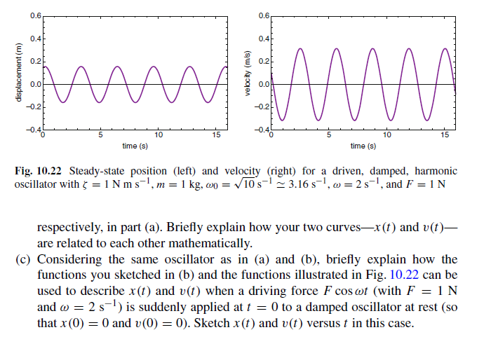
Problem 14: Approach to Steady State (a) Figure 10.22 shows the steady-state position (left) and velocity (right) versus time for a driven, damped, harmonic oscillator with 5 = 1 Nm s, m = 1 kg, wo = 10 s 3.16 s, w = 2 s, F = 1 N, and a driving force, F cos wt. From these figures or otherwise, estimate x(0) and v(0) in this case. Briefly explain how these curves would change (if at all) if the driving force were F sin wt instead of F cos cot. (b) Consider the same oscillator as in (a) with 5 = 1 Nm s, m = 1 kg, and wo = k/m=10 s, except that now there is no driving force (F = 0). Sketch the position and velocity of this damped, harmonic oscillator versus time, given that its initial position and velocity are given by your answers for x (0) and v(0), displacement (m) 0.6 0.4 0.2 0.0 -0.2 10 15 time (s) velocity (m/s) 0.6 0.4 0.2 0.0 -0.2 Mw 10 15 time (s) Fig. 10.22 Steady-state position (left) and velocity (right) for a driven, damped, harmonic oscillator with
Step by Step Solution
There are 3 Steps involved in it

Get step-by-step solutions from verified subject matter experts