

Question: Problem 2. Considering the feedback control system given in the figure on the RHS, where Gc(s)=K, and Gp(s)=s(s++2)(s+2+1)1 P2.1. Sketch the root locus by hand
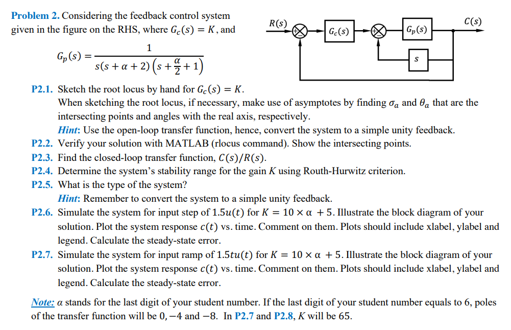
Problem 2. Considering the feedback control system given in the figure on the RHS, where Gc(s)=K, and Gp(s)=s(s++2)(s+2+1)1 P2.1. Sketch the root locus by hand for Gc(s)=K. When sketching the root locus, if necessary, make use of asymptotes by finding a and a that are the intersecting points and angles with the real axis, respectively. Hint: Use the open-loop transfer function, hence, convert the system to a simple unity feedback. P2.2. Verify your solution with MATLAB (rlocus command). Show the intersecting points. P2.3. Find the closed-loop transfer function, C(s)/R(s). P2.4. Determine the system's stability range for the gain K using Routh-Hurwitz criterion. P2.5. What is the type of the system? Hint: Remember to convert the system to a simple unity feedback. P2.6. Simulate the system for input step of 1.5u(t) for K=10+5. Illustrate the block diagram of your solution. Plot the system response c(t) vs. time. Comment on them. Plots should include xlabel, ylabel and legend. Calculate the steady-state error. P2.7. Simulate the system for input ramp of 1.5tu(t) for K=10+5. Illustrate the block diagram of your solution. Plot the system response c(t) vs. time. Comment on them. Plots should include xlabel, ylabel and legend. Calculate the steady-state error. Note: stands for the last digit of your student number. If the last digit of your student number equals to 6 , poles of the transfer function will be 0,4 and 8. In P2.7 and P2.8, K will be 65
Step by Step Solution
There are 3 Steps involved in it

Get step-by-step solutions from verified subject matter experts