

Question: Problem 2 Pipelining Consider the following combinational logic circuit constructed from 6 modules. In the diagram below, each combinational component is marked with its propagation
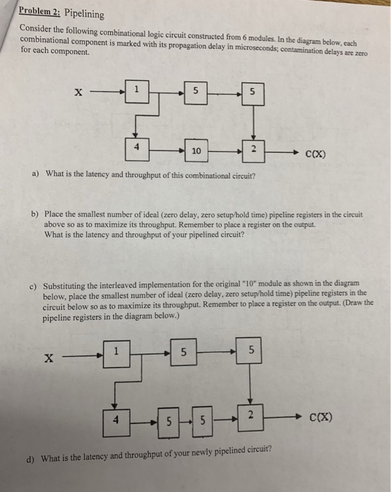
Problem 2 Pipelining Consider the following combinational logic circuit constructed from 6 modules. In the diagram below, each combinational component is marked with its propagation delay in microseconds; contamination delays are zero for each component. a) What is the latency and throughput of this combinational circuit? b) Place the smallest number of ideal (zero delay, zero setup/hold time) pipeline registers in the circuit above so as to maximize its throughput. Remember to place a register on the output. What is the latency and throughput of your pipelined circuit? Substituting the interleaved implementation for the original "10" module as shown in the diagram below, place the smallest number of ideal (zero delay, zero setup/hold time) pipeline registers in the circuit below so as to maximize its throughput. Remember to place a register on the output. (Draw the pipeline registers in the diagram below.) c) 1 -- 5 d) What is the latency and throughput of your newly pipelined circuit? Problem 2 Pipelining Consider the following combinational logic circuit constructed from 6 modules. In the diagram below, each combinational component is marked with its propagation delay in microseconds; contamination delays are zero for each component. a) What is the latency and throughput of this combinational circuit? b) Place the smallest number of ideal (zero delay, zero setup/hold time) pipeline registers in the circuit above so as to maximize its throughput. Remember to place a register on the output. What is the latency and throughput of your pipelined circuit? Substituting the interleaved implementation for the original "10" module as shown in the diagram below, place the smallest number of ideal (zero delay, zero setup/hold time) pipeline registers in the circuit below so as to maximize its throughput. Remember to place a register on the output. (Draw the pipeline registers in the diagram below.) c) 1 -- 5 d) What is the latency and throughput of your newly pipelined circuit
Step by Step Solution
There are 3 Steps involved in it

Get step-by-step solutions from verified subject matter experts