

Question: Problem 3 The continuous beam shown below is supported by columns at B and C ( both pin - connected ) and attached via a
Problem
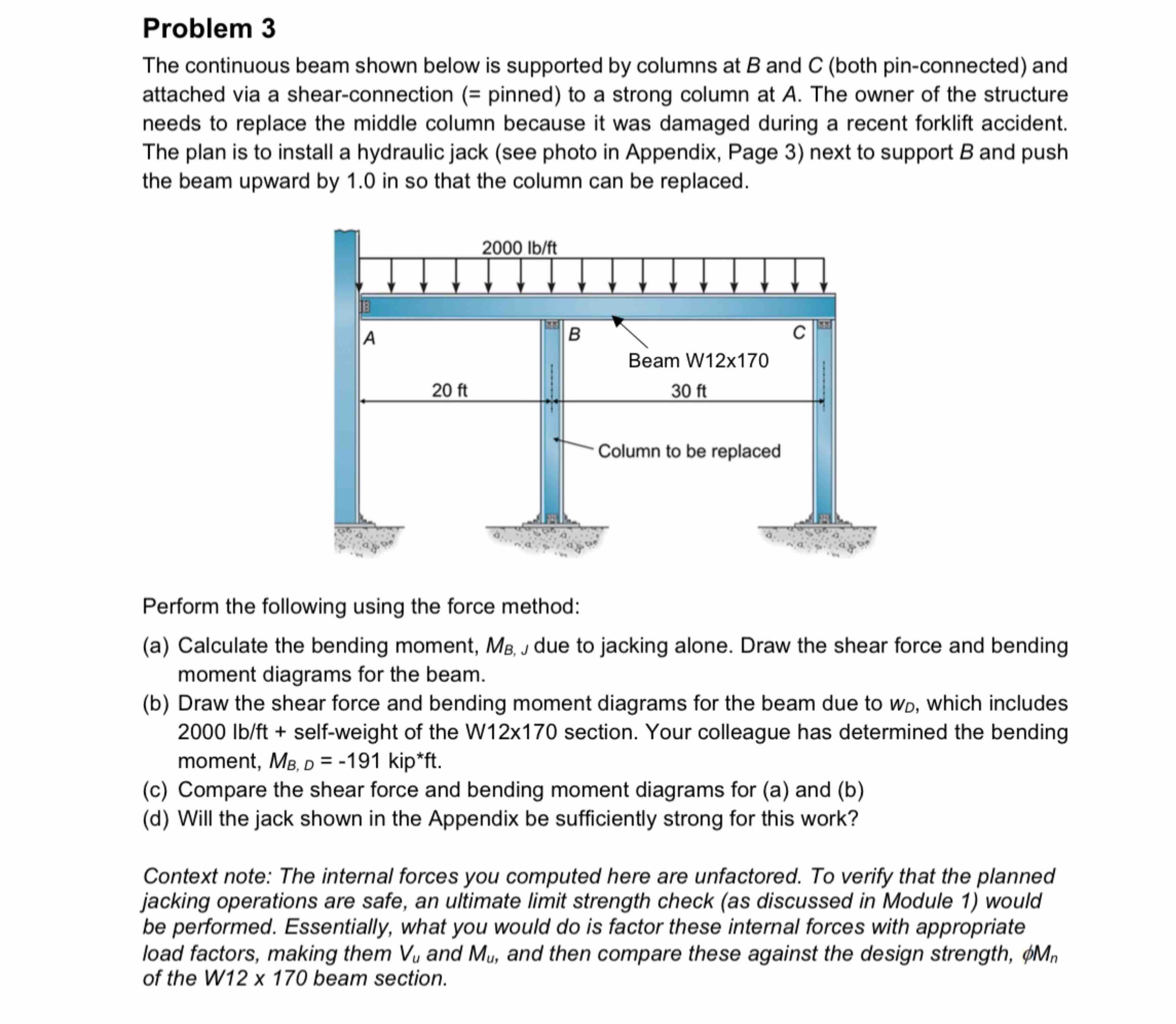
The continuous beam shown below is supported by columns at and both pinconnected and
attached via a shearconnection pinned to a strong column at The owner of the structure
needs to replace the middle column because it was damaged during a recent forklift accident.
The plan is to install a hydraulic jack see photo in Appendix, Page next to support and push
the beam upward by in so that the column can be replaced.
Perform the following using the force method:
a Calculate the bending moment, due to jacking alone. Draw the shear force and bending
moment diagrams for the beam.
b Draw the shear force and bending moment diagrams for the beam due to which includes
selfweight of the Wx section. Your colleague has determined the bending
moment, kipft
c Compare the shear force and bending moment diagrams for a and b
d Will the jack shown in the Appendix be sufficiently strong for this work?
Context note: The internal forces you computed here are unfactored. To verify that the planned
jacking operations are safe, an ultimate limit strength check as discussed in Module would
be performed. Essentially, what you would do is factor these internal forces with appropriate
load factors, making them and and then compare these against the design strength,
of the W beam section.
Step by Step Solution
There are 3 Steps involved in it
1 Expert Approved Answer
Step: 1 Unlock

Question Has Been Solved by an Expert!
Get step-by-step solutions from verified subject matter experts
Step: 2 Unlock
Step: 3 Unlock