

Question: Problem 3 The two - reservoir system shown in Figure 3 consists of three concrete pipes with roughness k s = 0 . 3 5
Problem
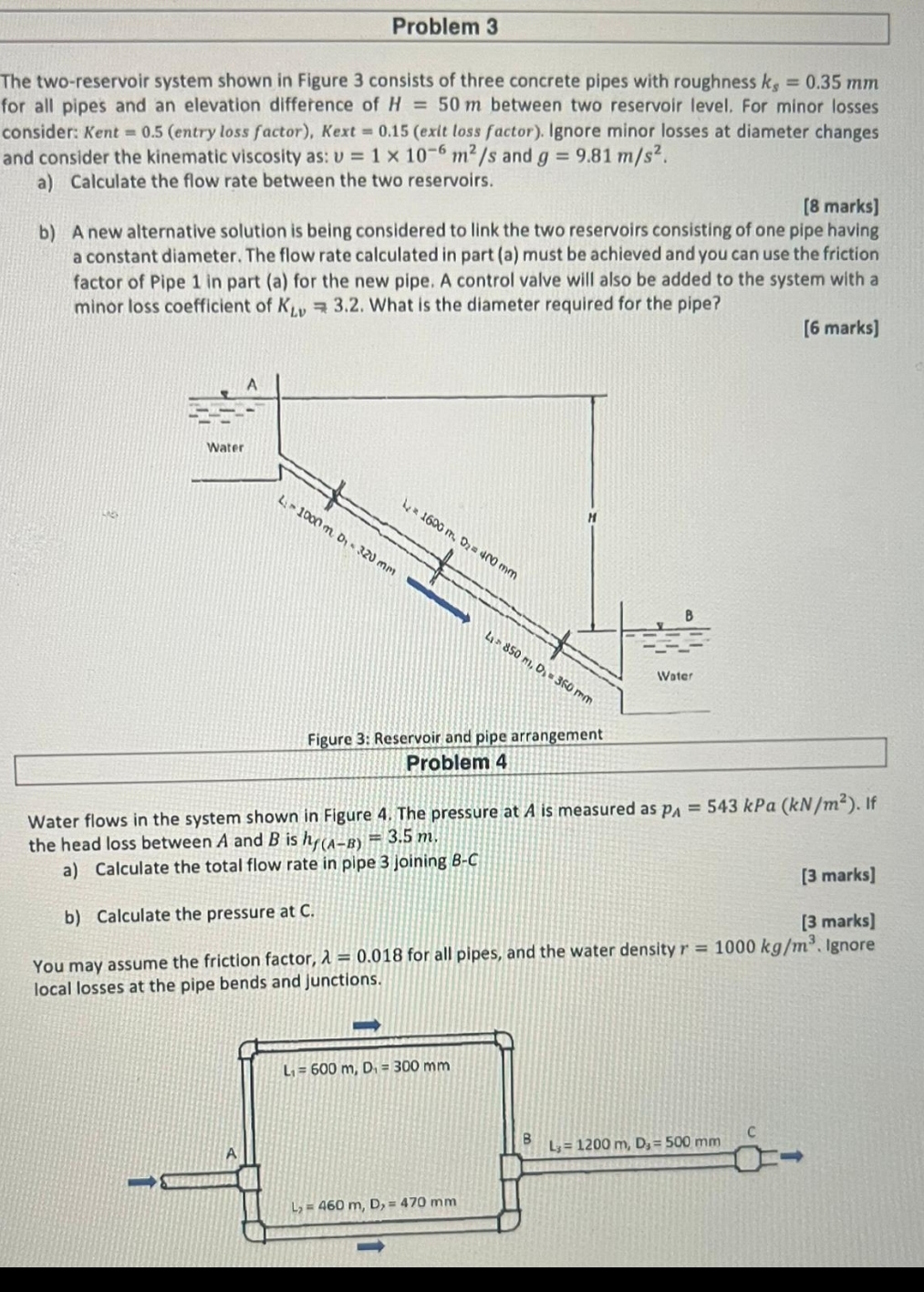
The tworeservoir system shown in Figure consists of three concrete pipes with roughness for all pipes and an elevation difference of between two reservoir level. For minor losses consider: Kent entry loss factor Kext exit loss factor Ignore minor losses at diameter changes and consider the kinematic viscosity as: and
a Calculate the flow rate between the two reservoirs.
marks
b A new alternative solution is being considered to link the two reservoirs consisting of one pipe having a constant diameter. The flow rate calculated in part a must be achieved and you can use the friction factor of Pipe in part a for the new pipe. A control valve will also be added to the system with a minor loss coefficient of
What is the diameter required for the pipe?
marks
Problem
Water flows in the system shown in Figure The pressure at is measured as kPa If the head loss between A and is
a Calculate the total flow rate in pipe joining
marks
b Calculate the pressure at
marks
You may assume the friction factor, for all pipes, and the water density Ignore local losses at the pipe bends and junctions.
I want detailed solution for both questions and i wanI want it urgently please do fast
Step by Step Solution
There are 3 Steps involved in it
1 Expert Approved Answer
Step: 1 Unlock

Question Has Been Solved by an Expert!
Get step-by-step solutions from verified subject matter experts
Step: 2 Unlock
Step: 3 Unlock