

Question: Problem 4. A block diagram for a divider that divides an 8-bit unsigned number by a 4-bit unsigned number to give a 4-bit quotient is
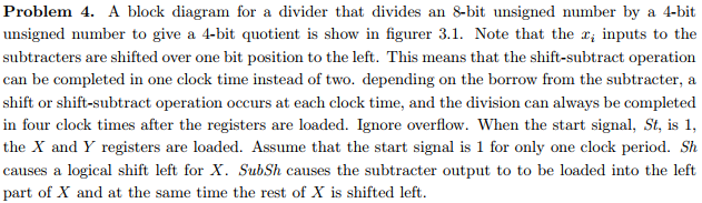
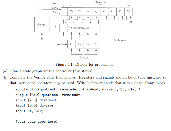
Problem 4. A block diagram for a divider that divides an 8-bit unsigned number by a 4-bit unsigned number to give a 4-bit quotient is show in figurer 3.1. Note that the r, inputs to the subtracters are shifted over one bit position to the left. This means that the shift-subtract operation can be completed in one clock time instead of two. depending on the borrow from the subtracter, a shift or shift-subtract operation occurs at each clock time, and the division can always be completed in four clock times after the registers are loaded. Ignore overflow. When the start signal, St, is 1, the X and Y registers are loaded. Assume that the start signal is 1 for only one clock period. Sh causes a logical shift left for X. SubSh causes the subtracter output to to be loaded into the left part of X and at the same time the rest of X is shifted left. Problem 4. A block diagram for a divider that divides an 8-bit unsigned number by a 4-bit unsigned number to give a 4-bit quotient is show in figurer 3.1. Note that the r, inputs to the subtracters are shifted over one bit position to the left. This means that the shift-subtract operation can be completed in one clock time instead of two. depending on the borrow from the subtracter, a shift or shift-subtract operation occurs at each clock time, and the division can always be completed in four clock times after the registers are loaded. Ignore overflow. When the start signal, St, is 1, the X and Y registers are loaded. Assume that the start signal is 1 for only one clock period. Sh causes a logical shift left for X. SubSh causes the subtracter output to to be loaded into the left part of X and at the same time the rest of X is shifted left
Step by Step Solution
There are 3 Steps involved in it

Get step-by-step solutions from verified subject matter experts