

Question: Problem 4 a) The circuit shown below shows one typical wait state generator implementation for the 8086/8088 microprocessors. 10 READY MRDC MWTC D PR o
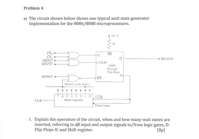
Problem 4 a) The circuit shown below shows one typical wait state generator implementation for the 8086/8088 microprocessors. 10 READY MRDC MWTC D PR o >> CLK DFF D-type flip-flop Q RS RESET Select wait states . . . 7 6 5 4 3 2 10 Shift register CLR CLK Data input I. Explain the operation of the circuit, when and how many wait states are inserted, referring to all input and output signals to/from logic gates, D- Flip-Flops IC and Shift register. [8p] II. Draw the wait state generation timing diagram for inserting three wait states. [5p] III. What is the maximum number of wait states that can be inserted? How can the number of wait states change? 12p)
Step by Step Solution
There are 3 Steps involved in it

Get step-by-step solutions from verified subject matter experts