

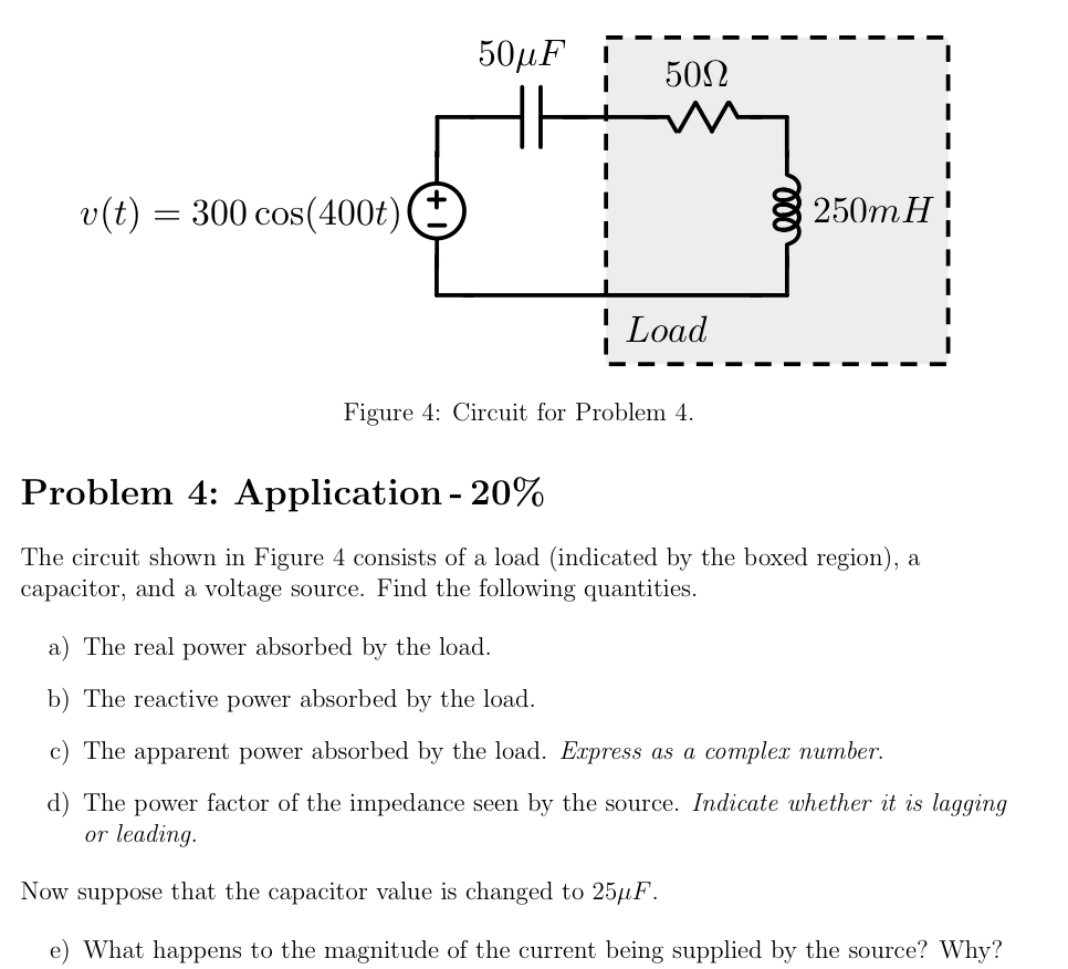
Question: Figure 4 : Circuit for Problem 4 . Problem 4 : Application - 2 0 % The circuit shown in Figure 4 consists of a
Figure : Circuit for Problem
Problem : Application
The circuit shown in Figure consists of a load indicated by the boxed region a capacitor, and a voltage source. Find the following quantities.
a The real power absorbed by the load.
b The reactive power absorbed by the load.
c The apparent power absorbed by the load. Express as a complex number.
d The power factor of the impedance seen by the source. Indicate whether it is lagging or leading.
Now suppose that the capacitor value is changed to
e What happens to the magnitude of the current being supplied by the source? Why?
Step by Step Solution
There are 3 Steps involved in it
1 Expert Approved Answer
Step: 1 Unlock

Question Has Been Solved by an Expert!
Get step-by-step solutions from verified subject matter experts
Step: 2 Unlock
Step: 3 Unlock