

Question: Problem 4 Consider the feedback control loop shown below. Its open loop system Bode plot for C(s)=K=1 is shown below. a) Design a (unity
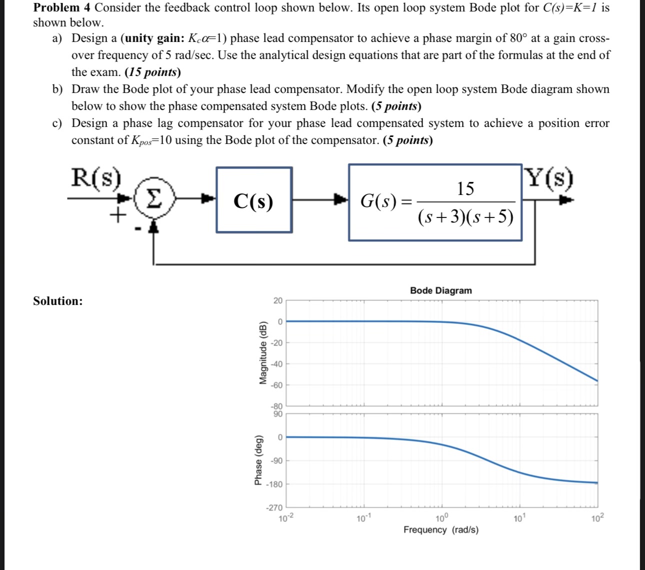
Problem 4 Consider the feedback control loop shown below. Its open loop system Bode plot for C(s)=K=1 is shown below. a) Design a (unity gain: Ke=1) phase lead compensator to achieve a phase margin of 80 at a gain cross- over frequency of 5 rad/sec. Use the analytical design equations that are part of the formulas at the end of the exam. (15 points) b) Draw the Bode plot of your phase lead compensator. Modify the open loop system Bode diagram shown below to show the phase compensated system Bode plots. (5 points) c) Design a phase lag compensator for your phase lead compensated system to achieve a position error constant of Kpos=10 using the Bode plot of the compensator. (5 points) Solution: R(s) + C(s) G(s) = 15 (s+3)(s+5) Y(s) Phase (deg) Magnitude (dB) -90 0 -20 -40 -60 -80 90 20 Bode Diagram -180 -270 10-2 10-1 10 Frequency (rad/s) 101 102
Step by Step Solution
There are 3 Steps involved in it

Get step-by-step solutions from verified subject matter experts