

Question: Problem 4 where K 1 is a positive constant. We also assume that the change in the inflow rate q i is negatively proportional to
Problem where is a positive constant. We also assume that the change in the inflow rate is
negatively proportional to the change in the valve opening or
where is a positive constant.
Assuming the following numerical values for the system,
obtain the transfer function
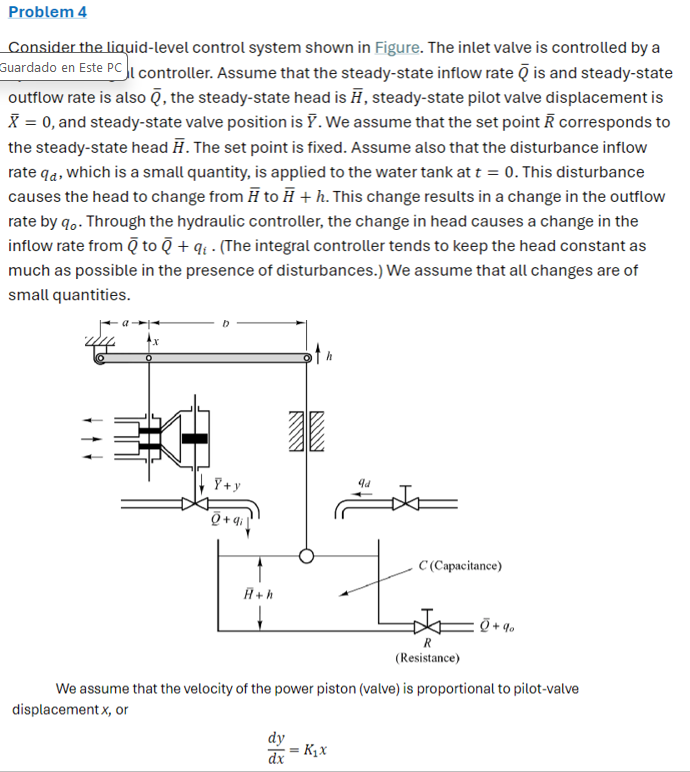
Consider the liquidlevel control system shown Figure. The inlet valve controlled
Guardado Este I controller. Assume that the steadystate inflow rate and steadystate
outflow rate also the steadystate head steadystate pilot valve displacement
and steadystate valve position assume that the set point corresponds
the steadystate head The set point fixed. Assume also that the disturbance inflow
rate which a small quantity, applied the water tank This disturbance
causes the head change from This change results a change the outflow
rate Through the hydraulic controller, the change head causes a change the
inflow rate from integral controller tends keep the head constant
much possible the presence disturbances. assume that all changes are
small quantities.
assume that the velocity the power piston proportional pilotvalve
displacement
Step by Step Solution
There are 3 Steps involved in it
1 Expert Approved Answer
Step: 1 Unlock

Question Has Been Solved by an Expert!
Get step-by-step solutions from verified subject matter experts
Step: 2 Unlock
Step: 3 Unlock