

Question: Problem 6 In the system shown below, the connections at A , C and E are pinned. Draw the internal axial force diagram for member
Problem
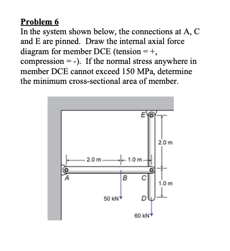
In the system shown below, the connections at
and E are pinned. Draw the internal axial force
diagram for member DCE tension
compression If the normal stress anywhere in
member DCE cannot exceed MPa determine
the minimum crosssectional area of member.
Step by Step Solution
There are 3 Steps involved in it
1 Expert Approved Answer
Step: 1 Unlock

Question Has Been Solved by an Expert!
Get step-by-step solutions from verified subject matter experts
Step: 2 Unlock
Step: 3 Unlock