

Question: ( Problem 6 ) The circuit shown in Figure P 6 . 6 3 can be used as a low - pass filter. a .
Problem
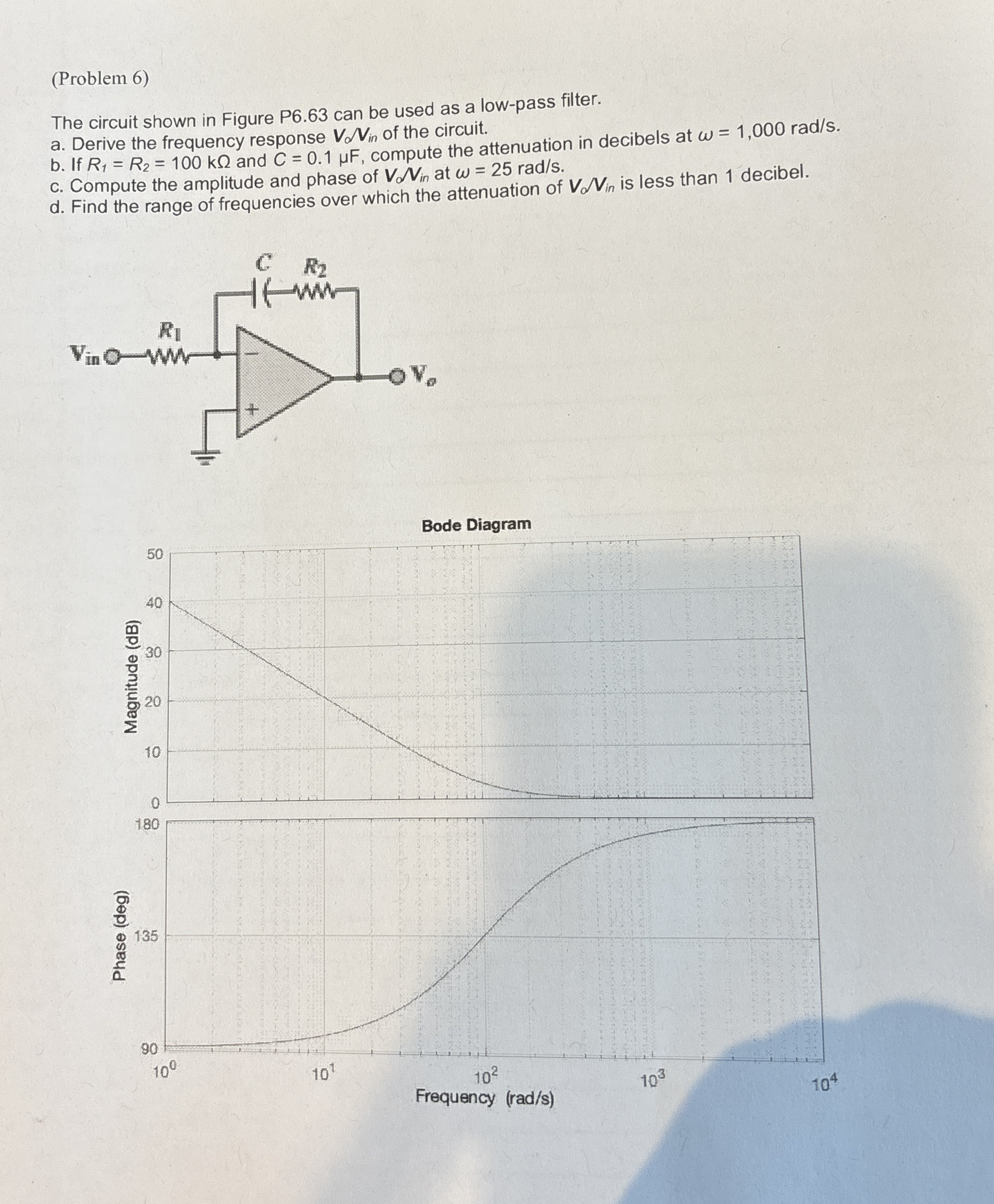
The circuit shown in Figure P can be used as a lowpass filter.
a Derive the frequency response of the circuit.
b If and compute the attenuation in decibels at
c Compute the amplitude and phase of at
d Find the range of frequencies over which the attenuation of is less than decibel.
Bode Diagram
Step by Step Solution
There are 3 Steps involved in it
1 Expert Approved Answer
Step: 1 Unlock

Question Has Been Solved by an Expert!
Get step-by-step solutions from verified subject matter experts
Step: 2 Unlock
Step: 3 Unlock