

Question: Problem AP2-14 The building shown at lower left has a length of 100 ft as shown, and its width (into the page) is also 100
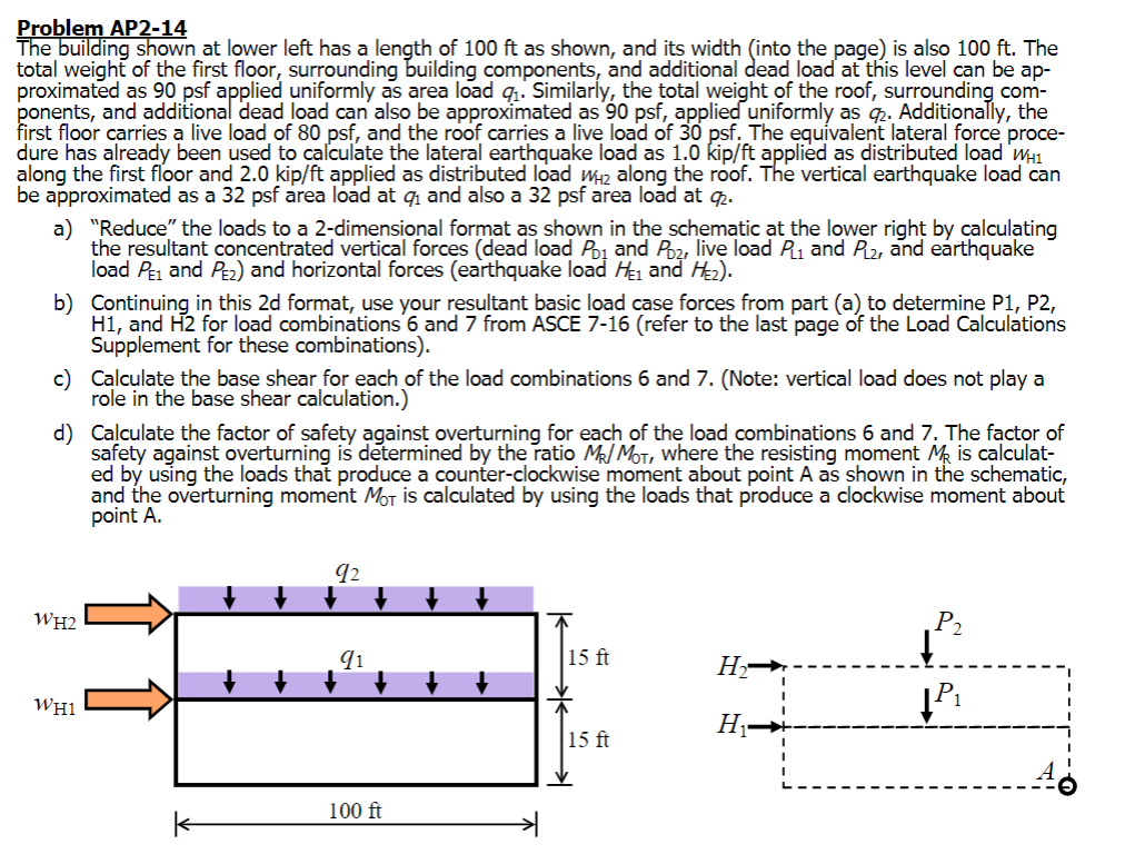
Problem AP2-14 The building shown at lower left has a length of 100 ft as shown, and its width (into the page) is also 100 ft. The total weight of the first floor, surrounding building components, and additional dead load at this level can be ap- proximated as 90 psf applied uniformly as area load q. Similarly, the total weight of the roof, surrounding com- ponents, and additional dead load can also be approximated as 90 psf, applied uniformly as 92. Additionally, the first floor carries a live load of 80 psf, and the roof carries a live load of 30 psf. The equivalent lateral force proce- dure has already been used to calculate the lateral earthquake load as 1.0 kip/ft applied as distributed load Whi along the first floor and 2.0 kip/ft applied as distributed load Wh2 along the roof. The vertical earthquake load can be approximated as a 32 psf area load at 91 and also a 32 psf area load at qz. a) "Reduce" the loads to a 2-dimensional format as shown in the schematic at the lower right by calculating the resultant concentrated vertical forces (dead load Poz and Poz, live load Pli and Plz, and earthquake load Pei and Pez) and horizontal forces (earthquake load Hen and H2). b) Continuing in this 2d format, use your resultant basic load case forces from part (a) to determine P1, P2, H1, and H2 for load combinations 6 and 7 from ASCE 7-16 (refer to the last page of the Load Calculations Supplement for these combinations). c) Calculate the base shear for each of the load combinations 6 and 7. (Note: vertical load does not play a role in the base shear calculation.) d) Calculate the factor of safety against overturning for each of the load combinations 6 and 7. The factor of safety against overturning is determined by the ratio M Mot, where the resisting moment MR is calculat- ed by using the loads that produce a counter-clockwise moment about point A as shown in the schematic, and the overturning moment Mor is calculated by using the loads that produce a clockwise moment about point A. 92 + WH2 P2 91 15 ft H- WHI 11 H 15 ft 100 ft k Problem AP2-14 The building shown at lower left has a length of 100 ft as shown, and its width (into the page) is also 100 ft. The total weight of the first floor, surrounding building components, and additional dead load at this level can be ap- proximated as 90 psf applied uniformly as area load q. Similarly, the total weight of the roof, surrounding com- ponents, and additional dead load can also be approximated as 90 psf, applied uniformly as 92. Additionally, the first floor carries a live load of 80 psf, and the roof carries a live load of 30 psf. The equivalent lateral force proce- dure has already been used to calculate the lateral earthquake load as 1.0 kip/ft applied as distributed load Whi along the first floor and 2.0 kip/ft applied as distributed load Wh2 along the roof. The vertical earthquake load can be approximated as a 32 psf area load at 91 and also a 32 psf area load at qz. a) "Reduce" the loads to a 2-dimensional format as shown in the schematic at the lower right by calculating the resultant concentrated vertical forces (dead load Poz and Poz, live load Pli and Plz, and earthquake load Pei and Pez) and horizontal forces (earthquake load Hen and H2). b) Continuing in this 2d format, use your resultant basic load case forces from part (a) to determine P1, P2, H1, and H2 for load combinations 6 and 7 from ASCE 7-16 (refer to the last page of the Load Calculations Supplement for these combinations). c) Calculate the base shear for each of the load combinations 6 and 7. (Note: vertical load does not play a role in the base shear calculation.) d) Calculate the factor of safety against overturning for each of the load combinations 6 and 7. The factor of safety against overturning is determined by the ratio M Mot, where the resisting moment MR is calculat- ed by using the loads that produce a counter-clockwise moment about point A as shown in the schematic, and the overturning moment Mor is calculated by using the loads that produce a clockwise moment about point A. 92 + WH2 P2 91 15 ft H- WHI 11 H 15 ft 100 ft k
Step by Step Solution
There are 3 Steps involved in it

Get step-by-step solutions from verified subject matter experts