

Question: 4-8 For the beam shown in Fig. P4-8, f = 3500 psi and fy = 60,000 psi. (a) Compute the effective flange width at
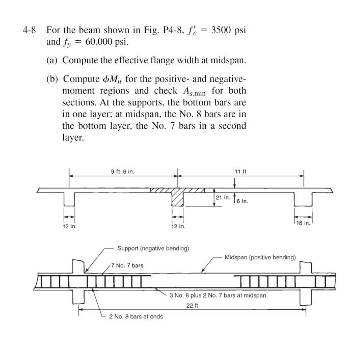
4-8 For the beam shown in Fig. P4-8, f = 3500 psi and fy = 60,000 psi. (a) Compute the effective flange width at midspan. (b) Compute Mn for the positive- and negative- moment regions and check As.min for both sections. At the supports, the bottom bars are in one layer; at midspan, the No. 8 bars are in the bottom layer, the No. 7 bars in a second layer. 12 in. 9 ft-6 in. 12 in. Support (negative bending) 7 No. 7 bars 2 No. 8 bars at ends 21 in. 11 ft 6 in. 18 in. Midspan (positive bending) 3 No. 8 plus 2 No. 7 bars at midspan 22 ft
Step by Step Solution
3.49 Rating (152 Votes )
There are 3 Steps involved in it
C085fbbc 9 Substitute 3500 psi for f 12 in for b 085 for P and 45 in for c in Equat... View full answer

Get step-by-step solutions from verified subject matter experts