

Question: Problem Statement Having completed and understood an implementation of the Client-Server paradigm using TCP, we have demonstrated that any two clients can communicate using a
Problem Statement Having completed and understood an implementation of the Client-Server paradigm using TCP, we have demonstrated that any two clients can communicate using a server- router as a bridge. The threading capability allows as many nodes as possible to be spawned for dynamic configurability and scalability of the network. This Part 2, which is based on the Peer-to-Peer (P2P) paradigm, will be explored for the next six (6) weeks.
Using the system from Part 1, the goal of Part 2 is to design and implement a P2P system based on the following architecture.
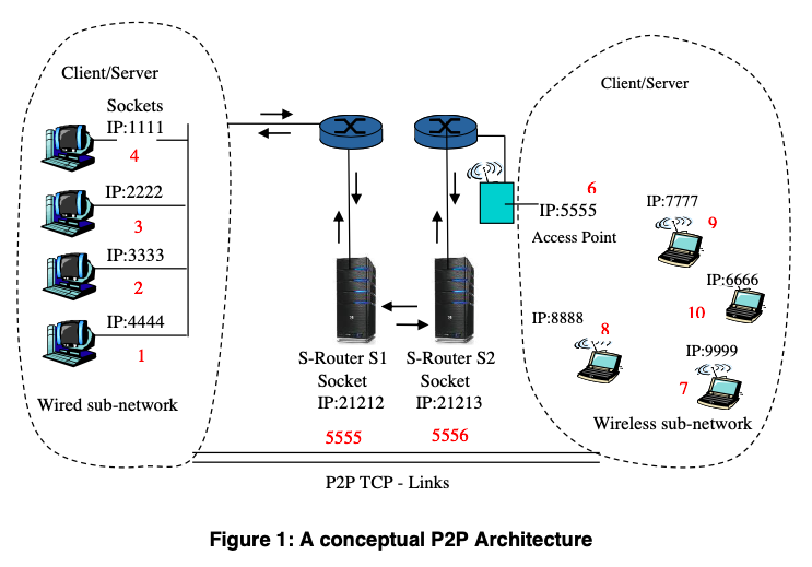
In the figure above, there are two clusters of user or client nodes. The desire is to have client-to-client or peer-to-peer TCP connections for direct communication, that is, without any intervening routers. However, this is not possible since the clients/peers have no knowledge of their respective IP addresses. This is where the Server-Routers (S-Routers, for short) come in. Each S-Router has in its routing tables ONLY the necessary routing information for all the clients/peers that are connected to it.
Now, suppose that a node N1 (in cluster/group N) desires to communicate directly with node M4 (in cluster/group M), then N1s S-Router will be consulted with a message which contains sufficient information for this S-Router to use. The S-Router for group N will then consult (by way of messaging) the S-Router for group M about the wish of node N1. Having node M4s information in its routing table, the S-Router for group M has no trouble working with the S-Router for group N to assist in creating a newTCP link for the exclusive use by N1 and M4. How the two routers assist in creating the new link is a part of your design choice for this architecture. The two routers job is done, or become decoupled, once the IP addresses of both N1 and M4 have been passed on to whoever creates the new link. From this point, N1 and M4 should be able to exchange messages or content information directly until they disconnect. This is the principle underlying most P2P systems such as Skype, Napster, Kazaa, and BitTorrent.
The IP numbers in Figure 1 are hypothetical. As before, use nslookup, ipconfig, or any tools on the PCs in the CSE Lab and/or your laptops you use in the configuration to determine the actual IP addresses. In the code from Part 1, these numbers and/or the symbolic names were either fixed (as strings) or hard-coded as IP-numbers.
What to Do and Turn In Using this basic architecture, and the solutions from Part 1, design the P2P system described above to allow as many pairs of nodes (from both clusters/groups) as possible or at least 100 pairs to exchange messages or content data. As before, let a text message sent in lower-case be converted to uppercase and returned. You may replace the text-file with something more meaningful or practical such as videos and audio file. If so, then replace the character-conversion logic inside the server-side code to reflect this new application.
Using the programs from Part 1, either in their original or modified forms, clone the S-Router code and modify the routing tables such that the nodes in each cluster have their IPs and other relevant information in the tables. Think of how a new pair of TCP sockets can be created between the pair of clients/peers. Think of this in the light of creating a new TCP socket for, e.g., N1, while it waits on its initial request to the S-Router for group N; and also how the S-Router for group M instructs node M1, for example, to connect to N1 using this new TCP link. Make use of the threading code and be careful of creating several sockets and leaving them open (not closed) at the same time. You need to work this logic until it holds. Note that the S-Router-S1 and S-Router-S2 communicate using a pair of TCP sockets with port numbers 5555 and 5556 respectively.
Again, make sure your test files exist on any node which is designated as a sender-Client/Peer. As before, collect and analyze data for such parameters as average message sizes, average transmission time, average time for the routing-table lookup, number of bytes/units of data transferred per unit time, average number of message drops (if any), and any other parameters of interest which is already built into the given code. Verify if the content type, text versus video versus audio, makes a difference in the systems performance.
Figure 1: A conceptual P2P Architecture
Step by Step Solution
There are 3 Steps involved in it

Get step-by-step solutions from verified subject matter experts