

Question: Process: 1. Interpret each instruction line and give a summary comment of what that instruction is accomplishing. 2. Complete a register purpose table that explains
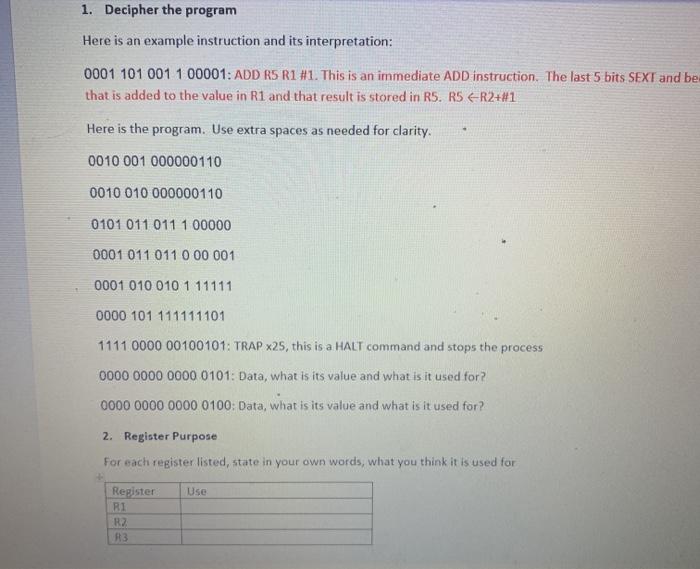
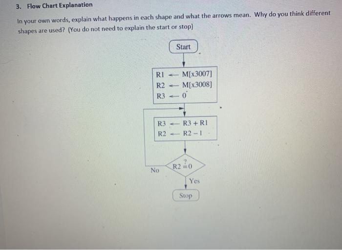
Process: 1. Interpret each instruction line and give a summary comment of what that instruction is accomplishing. 2. Complete a register purpose table that explains what each temporary registers job is. 3. Give a summary description for each shape in the flow chart (be sure to include a description for any arrows). 1. Decipher the program Here is an example instruction and its interpretation: 0001 101 001 1 00001: ADD R5 R1 #1. This is an immediate ADD Instruction. The last 5 bits SEXT and be that is added to the value in R1 and that result is stored in RS. R5 R2+#1 Here is the program. Use extra spaces as needed for clarity. 0010 001 000000110 0010 010 000000110 0101 011011 1 00000 0001 011 0110 00 001 0001 010 010 1 11111 0000 101 111111101 1111 0000 00100101: TRAP x25, this is a HALT command and stops the process 0000 0000 0000 0101: Data, what is its value and what is it used for? 0000 0000 0000 0100: Data, what is its value and what is it used for? 2. Register Purpose For each register listed, state in your own words, what you think it is used for Use Register RI RZ R3 3. Flow Chart Explanation In your own words, explain what happens in each shape and what the arrows mean. Why do you think different shapes are used? (You do not need to explain the start or stop) Start RI R2 R3 M[x3007) M[X3008] 0 R3 R2 R3+RI R2-1 R220 No Yes Stop
Step by Step Solution
There are 3 Steps involved in it

Get step-by-step solutions from verified subject matter experts