

Question: Project - 1 The following simplified structure is inspired by a manual powered mobile crane. Figure 1 . Crane Structure Design the system given as
Project
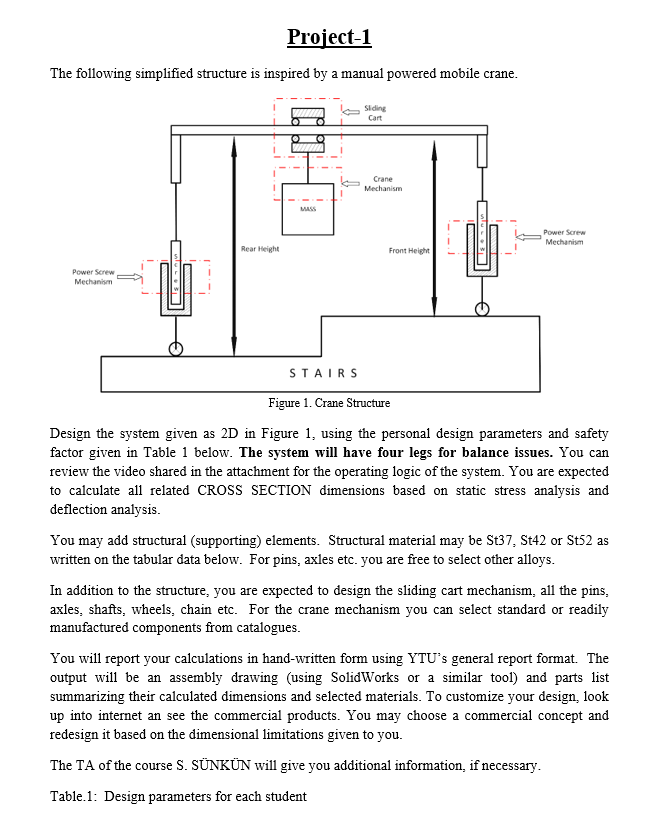
The following simplified structure is inspired by a manual powered mobile crane.
Figure Crane Structure
Design the system given as D in Figure using the personal design parameters and safety factor given in Table below. The system will have four legs for balance issues. You can review the video shared in the attachment for the operating logic of the system. You are expected to calculate all related CROSS SECTION dimensions based on static stress analysis and deflection analysis.
You may add structural supporting elements. Structural material may be St St or St as written on the tabular data below. For pins, axles etc. you are free to select other alloys.
In addition to the structure, you are expected to design the sliding cart mechanism, all the pins, axles, shafts, wheels, chain etc. For the crane mechanism you can select standard or readily manufactured components from catalogues.
You will report your calculations in handwritten form using YTU's general report format. The output will be an assembly drawing using SolidWorks or a similar tool and parts list summarizing their calculated dimensions and selected materials. To customize your design, look up into internet an see the commercial products. You may choose a commercial concept and redesign it based on the dimensional limitations given to you.
The TA of the course S SNKN will give you additional information, if necessary.
Table: Design parameters for each student
Step by Step Solution
There are 3 Steps involved in it
1 Expert Approved Answer
Step: 1 Unlock

Question Has Been Solved by an Expert!
Get step-by-step solutions from verified subject matter experts
Step: 2 Unlock
Step: 3 Unlock