

Question: Project Name: - _ ( A ) DC _ ( L ) ED _ ( B ) ar _ ( G ) raph Description: -
Project Name:
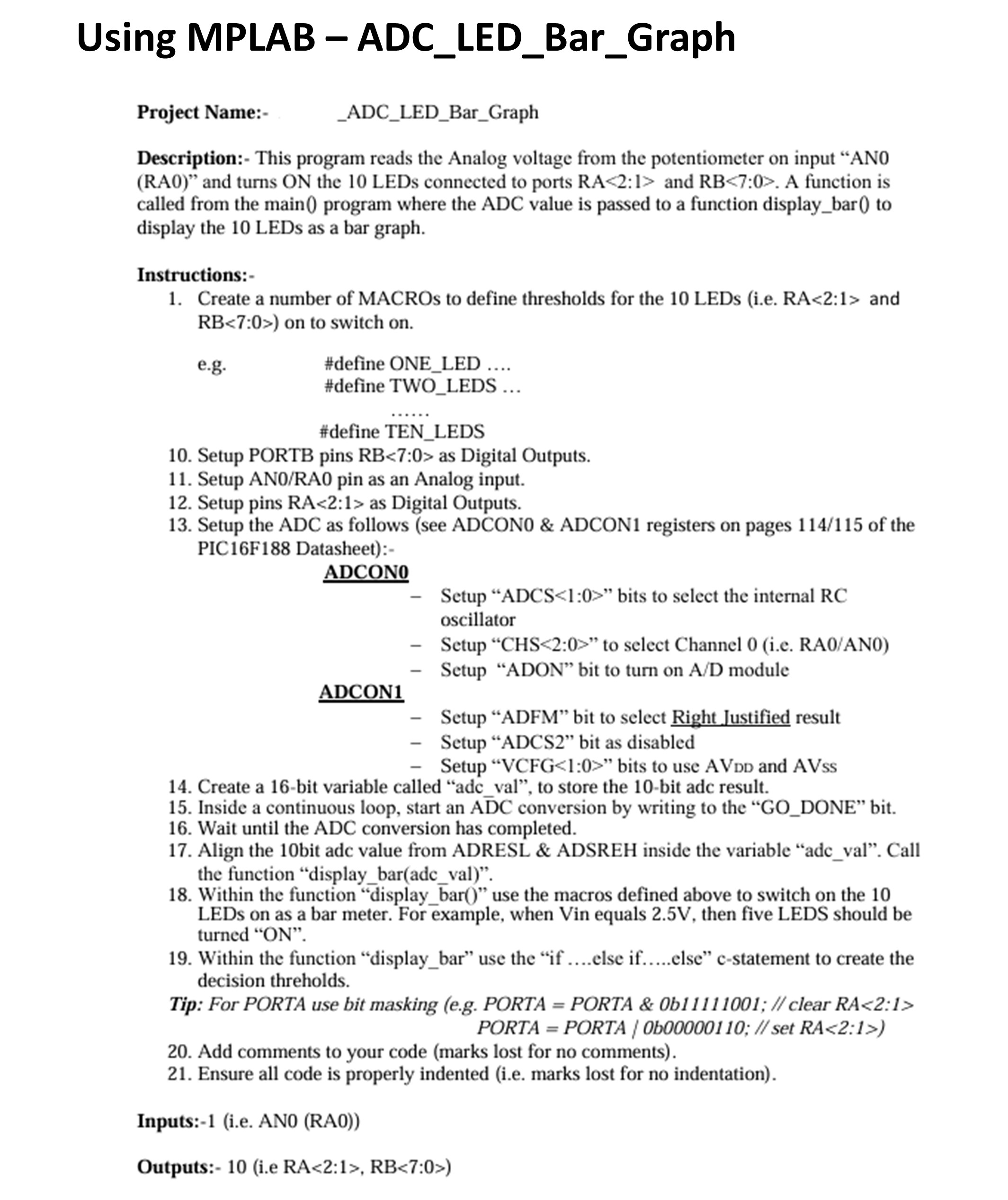
ADCLEDBarGraph
Description: This program reads the Analog voltage from the potentiometer on input AN
RA and turns ON the LEDs connected to ports RA : and RB:RB:#define ONELED
#define TWOLEDS
#define TENLEDS
Setup PORTB pins RB: as Digital Outputs.
Setup ANRA pin as an Analog input.
Setup pins RA: as Digital Outputs.
Setup the ADC as follows see ADCON & ADCON registers on pages of the
PICF Datasheet:
ADCON
Setup "ADCS : bits to select the internal RC
oscillator
Setup CHS: to select Channel ie RAAN
Setup "ADON" bit to turn on AD module
ADCON
Setup "ADFM" bit to select Right Justified result
Setup "ADCS bit as disabled
Setup VCFG: bits to use AVDD and AVss
Create a bit variable called "adcval to store the bit adc result.
Inside a continuous loop, start an Abar DC:RB:
Step by Step Solution
There are 3 Steps involved in it
1 Expert Approved Answer
Step: 1 Unlock

Question Has Been Solved by an Expert!
Get step-by-step solutions from verified subject matter experts
Step: 2 Unlock
Step: 3 Unlock