

Question: Project Name: - ADC _ ( L ) CD Description: - This program reads the Analog voltage from the potentiometer on input AN 0
Project Name:
ADCLCD
Description: This program reads the Analog voltage from the potentiometer on input AN
RA and displays the Bit ADC result ie on the first row of an LCD display. It
also displays the calculated Analog Input voltage on the nd row of the LCD display.
Add the file "lcd.h to the Header Files folder and "lcd.c Source Files folder as sohwn
below to the project in MPLABx:
Include the "lcd.h within "main.c:
#include LLCD lcdh
Create a macro name for ON and OFF :
Eg #define ON
#define OFF
Setup PORTB pins RB : as Digital Outputs.
Setup ANRA pin as an Analog input.
Setup the ADC as follows see ADCON & ADCON registers on pages of the
PICF Datasheet:
ADCON
Setup ADCS : bits to select the internal RC
Create a bit variable called "adc val", to store the bit adc result.
Inside a continuous loop, start an ADC conversion by writing to the GODONE bit.
Wait until the ADC conversion has completed.
Align the bit ade value from ADRESL & ADSREH inside the variable "adcval Call
the function "display baradcval
Calculate the value of vin using the following calculation:
vin float adcval ;
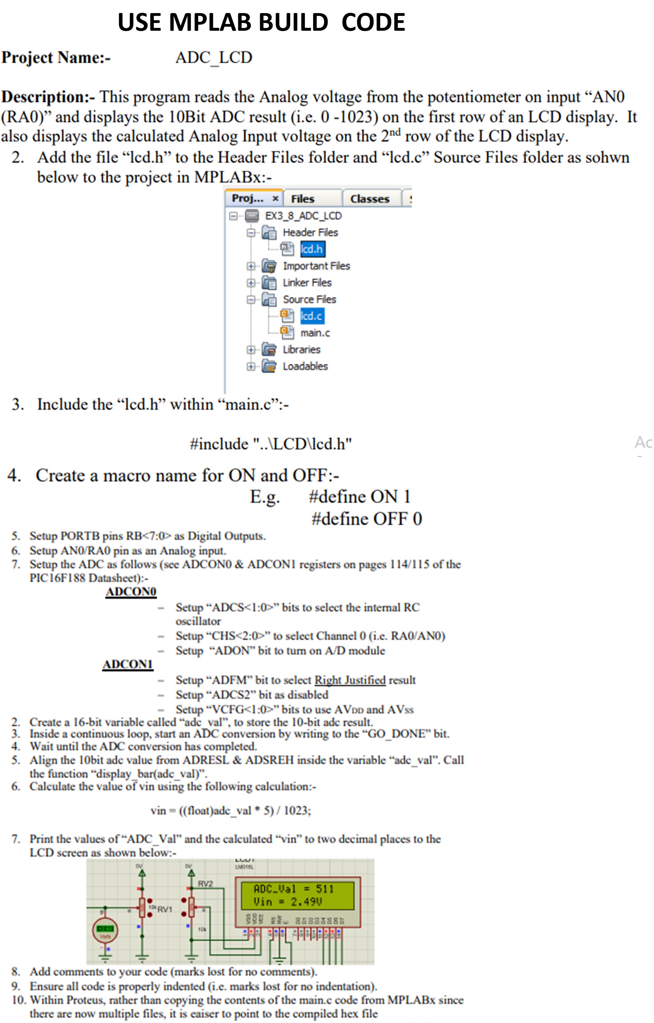
Print the values of "ADCVal and the calculated "vin" to two decimal places to the
LCD screer ne shown halow.
Add comments to your coade marks lost ior no comments
Ensure all code is properly indented ie marks lost for no indentation
Within Proteus, rather than copying the contents of the main.c code from MPLABx since
there are now multiple files, it is eaiser to point to the compiled hex file
Step by Step Solution
There are 3 Steps involved in it
1 Expert Approved Answer
Step: 1 Unlock

Question Has Been Solved by an Expert!
Get step-by-step solutions from verified subject matter experts
Step: 2 Unlock
Step: 3 Unlock