

Question: Q 1 . AP 1 5 . 4 - b . A second - order filter circuit is shown in the figure. Derive the transfer
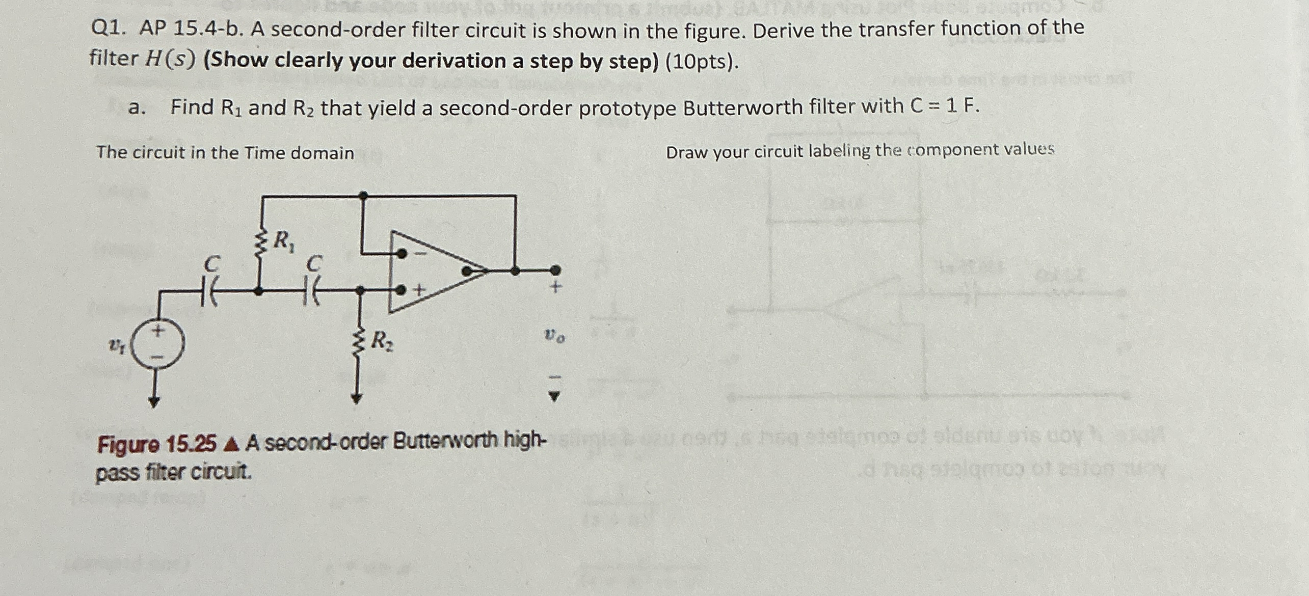
Q AP b A secondorder filter circuit is shown in the figure. Derive the transfer function of the filter Show clearly your derivation a step by steppts
a Find and that yield a secondorder prototype Butterworth filter with
The circuit in the Time domain
Figure secondorder Butterworth highpass filter circuit.
Draw your circuit labeling the component values
Step by Step Solution
There are 3 Steps involved in it
1 Expert Approved Answer
Step: 1 Unlock

Question Has Been Solved by an Expert!
Get step-by-step solutions from verified subject matter experts
Step: 2 Unlock
Step: 3 Unlock