

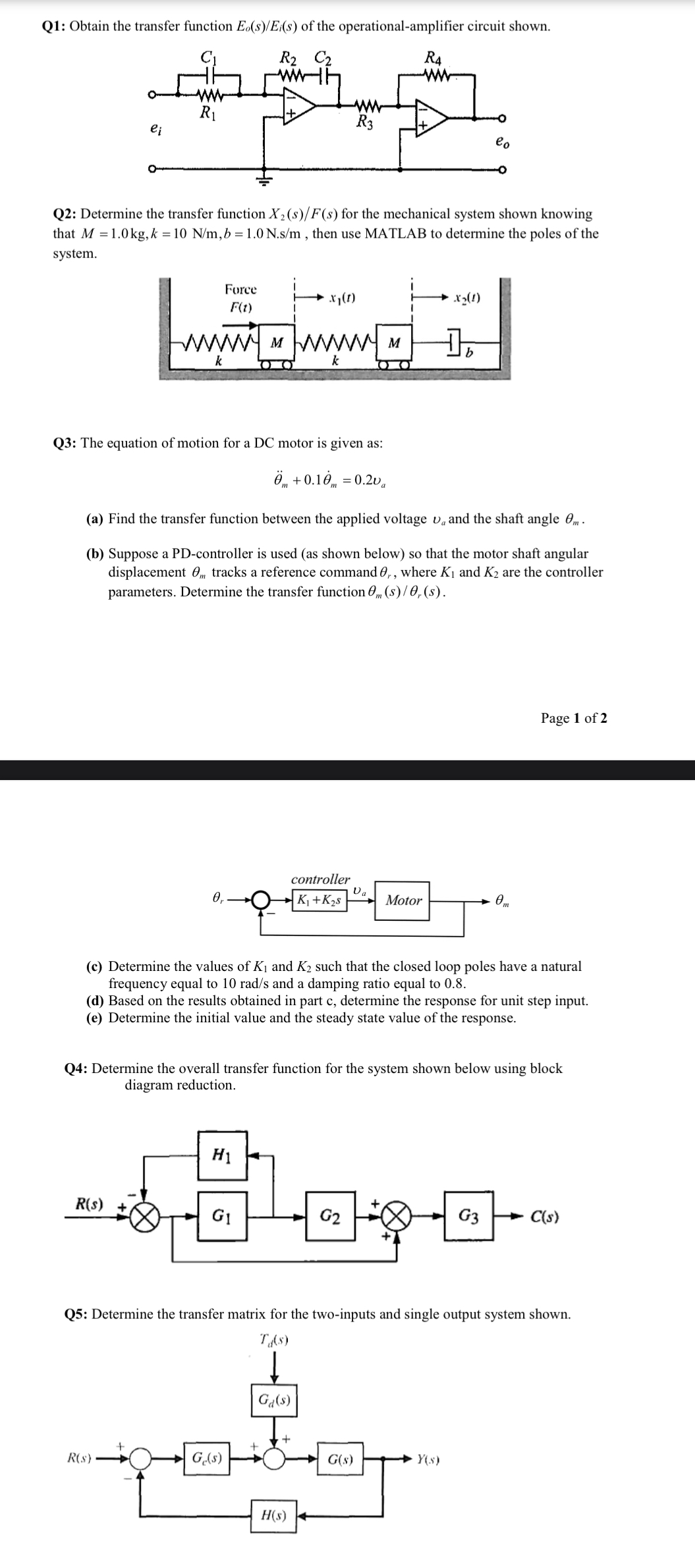
Question: Q 1 : Obtain the transfer function E o s E i ( s ) of the operational - amplifier circuit shown. Q 2 :
Q: Obtain the transfer function of the operationalamplifier circuit shown.
Q: Determine the transfer function for the mechanical system shown knowing that then use MATLAB to determine the poles of the system.
Q: The equation of motion for a DC motor is given as:
a Find the transfer function between the applied voltage and the shaft angle
b Suppose a PDcontroller is used as shown below so that the motor shaft angular displacement tracks a reference command where and are the controller parameters. Determine the transfer function
Page of
c Determine the values of and such that the closed loop poles have a natural frequency equal to and a damping ratio equal to
d Based on the results obtained in part c determine the response for unit step input.
e Determine the initial value and the steady state value of the response.
Q: Determine the overall transfer function for the system shown below using block diagram reduction.
Q: Determine the transfer matrix for the twoinputs and single output system shown.
Step by Step Solution
There are 3 Steps involved in it
1 Expert Approved Answer
Step: 1 Unlock

Question Has Been Solved by an Expert!
Get step-by-step solutions from verified subject matter experts
Step: 2 Unlock
Step: 3 Unlock