

Question: Q 2 . A full - wave bridge rectifier circuit is shown in Fig. Q 5 . Forward voltage of each diode is 0 .
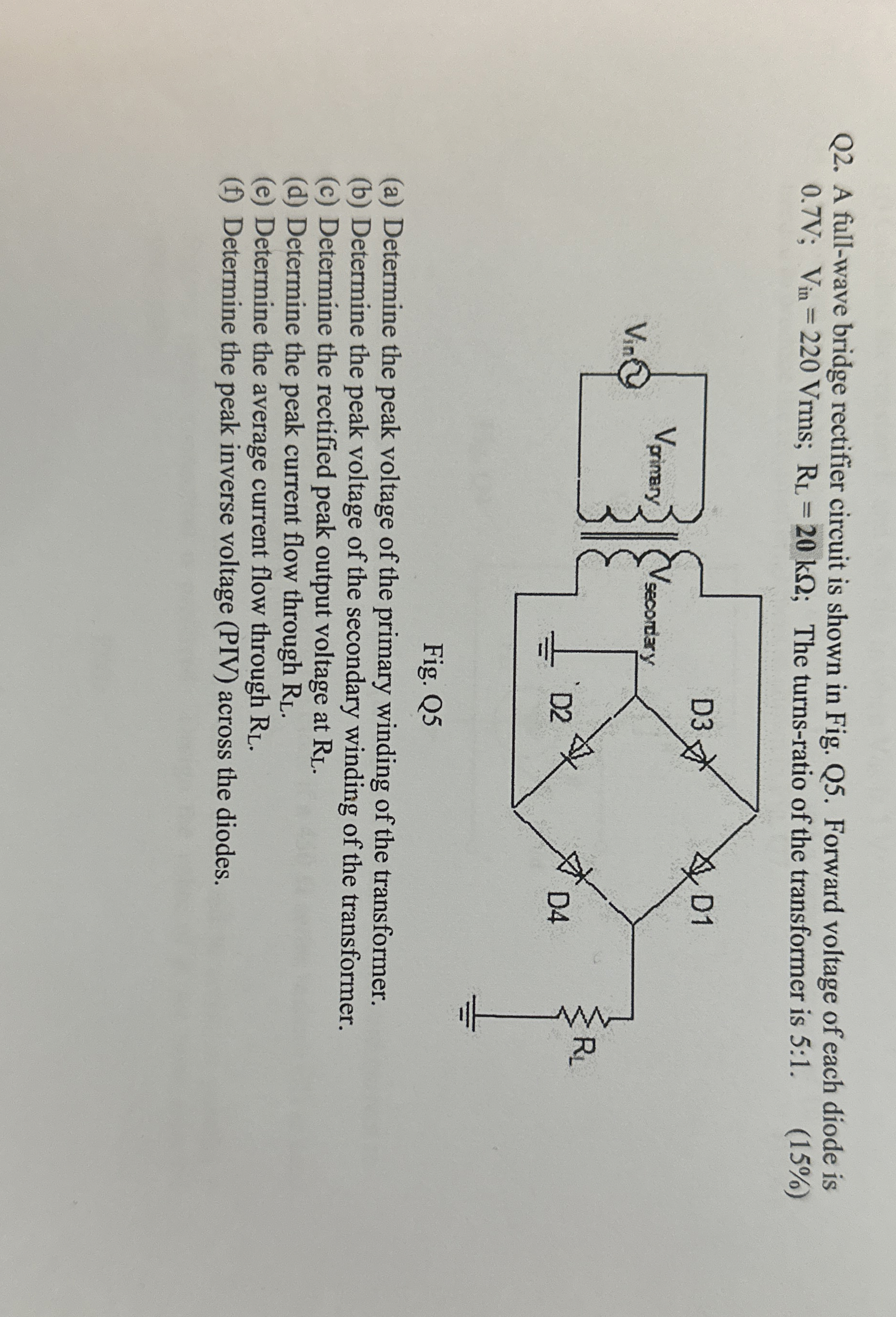
Q A fullwave bridge rectifier circuit is shown in Fig. Q Forward voltage of each diode is ;;; The turnsratio of the transformer is :
Fig. Q
a Determine the peak voltage of the primary winding of the transformer.
b Determine the peak voltage of the secondary winding of the transformer.
c Determine the rectified peak output voltage at
d Determine the peak current flow through
e Determine the average current flow through
f Determine the peak inverse voltage PIV across the diodes.
Step by Step Solution
There are 3 Steps involved in it
1 Expert Approved Answer
Step: 1 Unlock

Question Has Been Solved by an Expert!
Get step-by-step solutions from verified subject matter experts
Step: 2 Unlock
Step: 3 Unlock