

Question: Q 2 . P 1 5 . 3 6 . A second - order bandpass filter circuit is shown in the figure. Derive the transfer
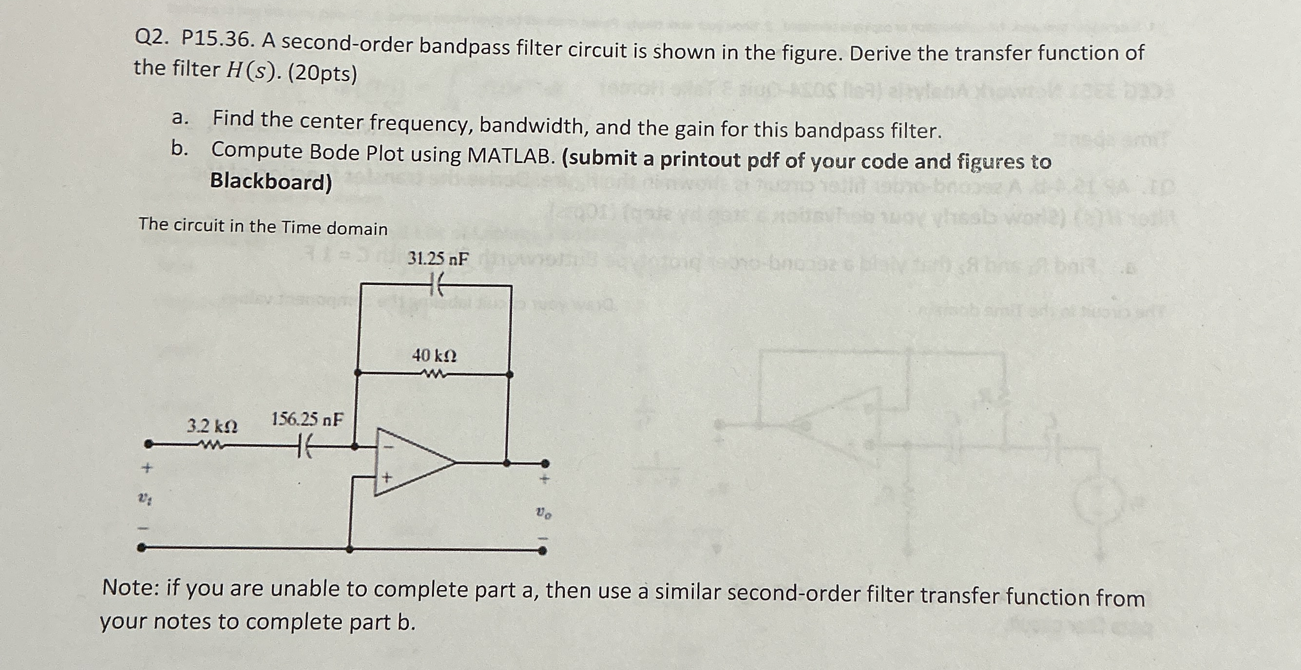
Q P A secondorder bandpass filter circuit is shown in the figure. Derive the transfer function of the filter pts
a Find the center frequency, bandwidth, and the gain for this bandpass filter.
b Compute Bode Plot using MATLAB. submit a printout pdf of your code and figures to Blackboard
The circuit in the Time domain
Note: if you are unable to complete part a then use a similar secondorder filter transfer function from your notes to complete part b
Step by Step Solution
There are 3 Steps involved in it
1 Expert Approved Answer
Step: 1 Unlock

Question Has Been Solved by an Expert!
Get step-by-step solutions from verified subject matter experts
Step: 2 Unlock
Step: 3 Unlock