

Question: Q 2 ) Simulate the circuit given in Figure 4 . 5 . 2 . Figure 4 . 5 . 2 ( 1 0 p
Q Simulate the circuit given in Figure
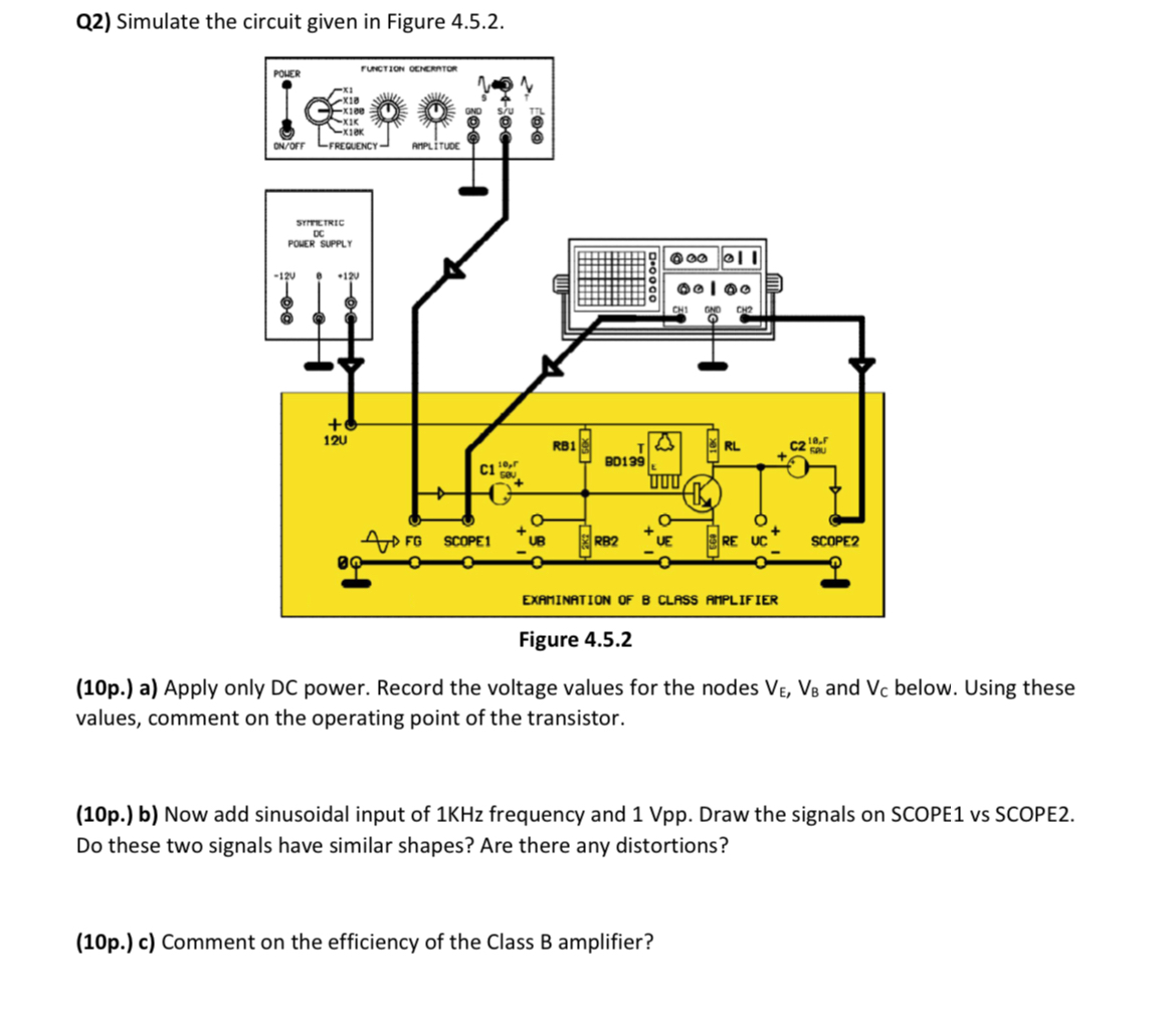
Figure
p a Apply only power. Record the voltage values for the nodes and below. Using these values, comment on the operating point of the transistor.
p b Now add sinusoidal input of KHz frequency and Vpp Draw the signals on SCOPE vs SCOPE Do these two signals have similar shapes? Are there any distortions?
p c Comment on the efficiency of the Class B amplifier? USE ADS PROGRAM TO SMULATE
Step by Step Solution
There are 3 Steps involved in it
1 Expert Approved Answer
Step: 1 Unlock

Question Has Been Solved by an Expert!
Get step-by-step solutions from verified subject matter experts
Step: 2 Unlock
Step: 3 Unlock