

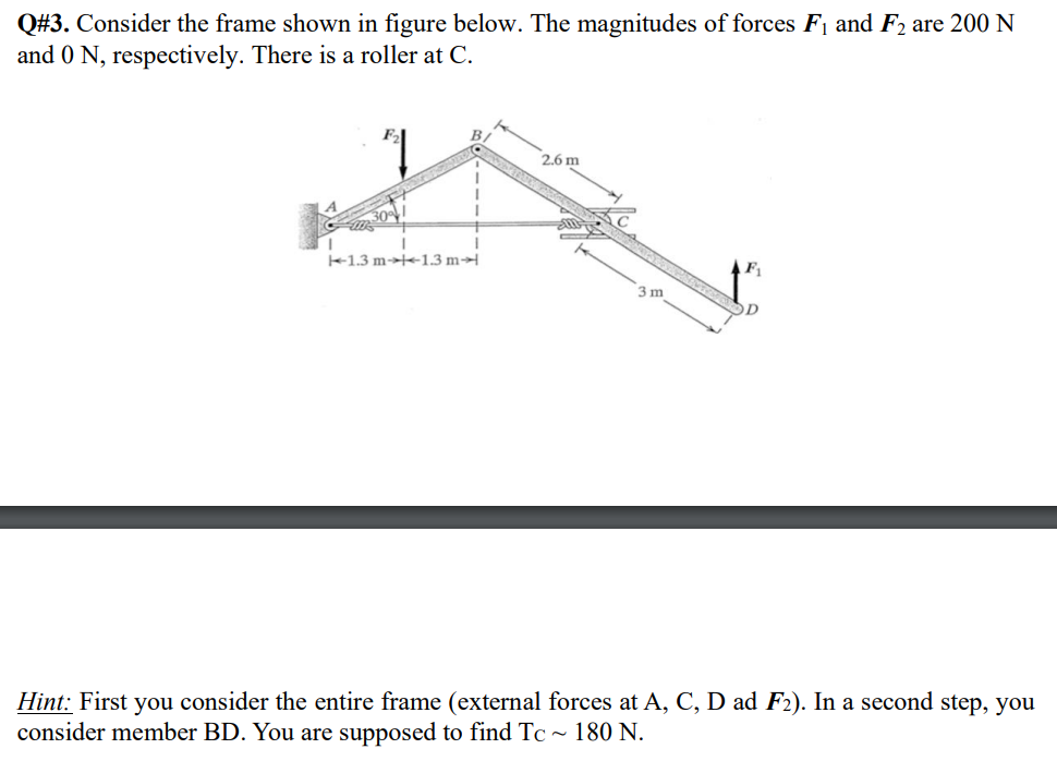
Question: Q# 3 . Consider the frame shown in figure below. The magnitudes of forces F 1 and F 2 are 2 0 0 N and
Q# Consider the frame shown in figure below. The magnitudes of forces and are N
and N respectively. There is a roller at C
Hint: First you consider the entire frame external forces at A C D ad In a second step, you
consider member BD You are supposed to find
Step by Step Solution
There are 3 Steps involved in it
1 Expert Approved Answer
Step: 1 Unlock

Question Has Been Solved by an Expert!
Get step-by-step solutions from verified subject matter experts
Step: 2 Unlock
Step: 3 Unlock