

Question: Q . 4 . A 6 5 0 N force is applied at the end C of the lever ABC shown in Fig. 2 .
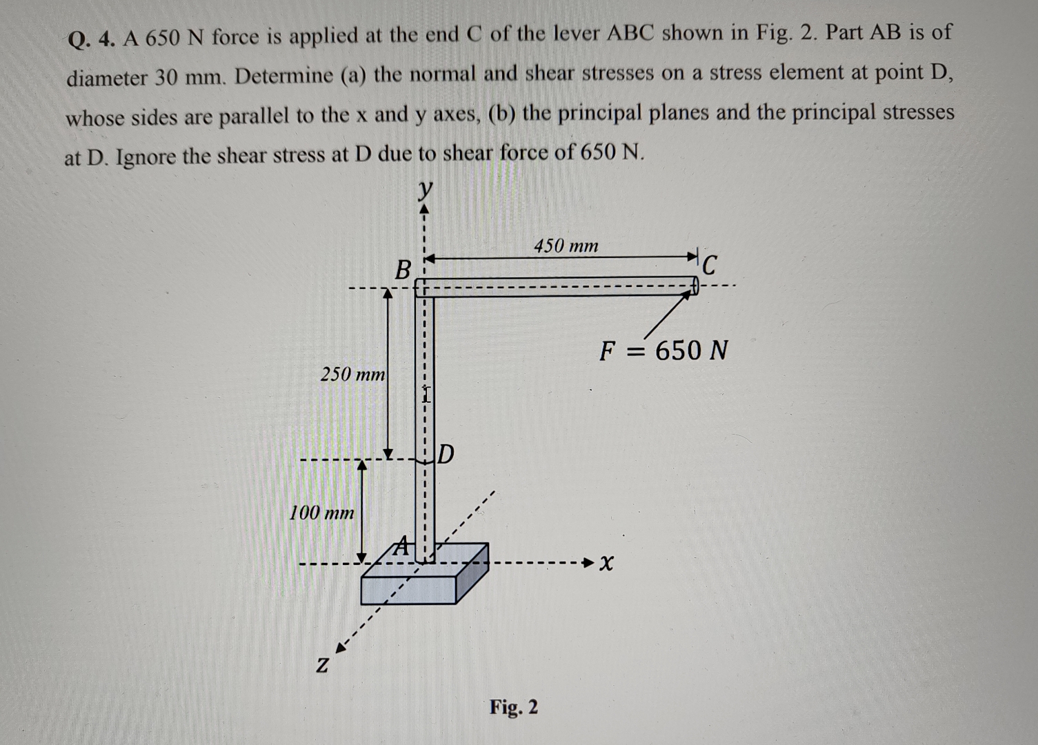
Q A N force is applied at the end C of the lever ABC shown in Fig. Part AB is of diameter mm Determine a the normal and shear stresses on a stress element at point whose sides are parallel to the x and y axes, b the principal planes and the principal stresses at D Ignore the shear stress at D due to shear force of N
Fig.
Step by Step Solution
There are 3 Steps involved in it
1 Expert Approved Answer
Step: 1 Unlock

Question Has Been Solved by an Expert!
Get step-by-step solutions from verified subject matter experts
Step: 2 Unlock
Step: 3 Unlock