

Question: Q 4 . The structure shown in Figure Q 4 is to he desioned elastically Figure Q 4 A two - span continuous beams with
Q
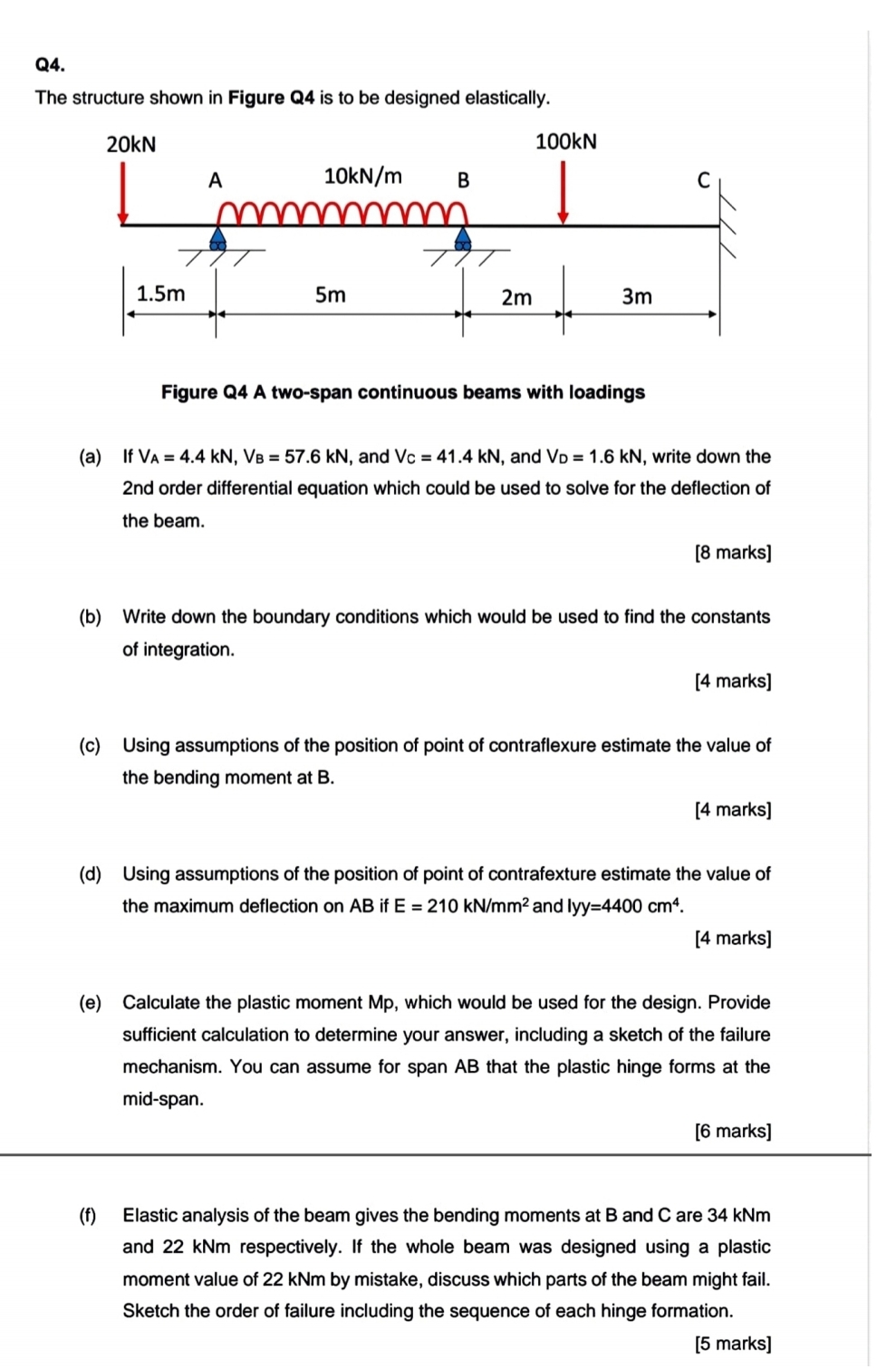
The structure shown in Figure is to he desioned elastically
Figure Q A twospan continuous beams with loadings
a If and and write down the nd order differential equation which could be used to solve for the deflection of the beam.
marks
b Write down the boundary conditions which would be used to find the constants of integration.
marks
c Using assumptions of the position of point of contraflexure estimate the value of the bending moment at B
marks
d Using assumptions of the position of point of contrafexture estimate the value of the maximum deflection on if and lyy
marks
e Calculate the plastic moment Mp which would be used for the design. Provide sufficient calculation to determine your answer, including a sketch of the failure mechanism. You can assume for span that the plastic hinge forms at the midspan.
marks
f Elastic analysis of the beam gives the bending moments at B and C are kNm and kNm respectively. If the whole beam was designed using a plastic moment value of kNm by mistake, discuss which parts of the beam might fail. Sketch the order of failure including the sequence of each hinge formation.
marks
i neeI need urgent solution for rhithis question.
please ealcall sub part
plydo it urgently
Step by Step Solution
There are 3 Steps involved in it
1 Expert Approved Answer
Step: 1 Unlock

Question Has Been Solved by an Expert!
Get step-by-step solutions from verified subject matter experts
Step: 2 Unlock
Step: 3 Unlock