

Question: Q4- A piezoelectric force sensor is connected to a voltage recorder of resistance RL by a cable of capacitance Cc. In terms of the electric
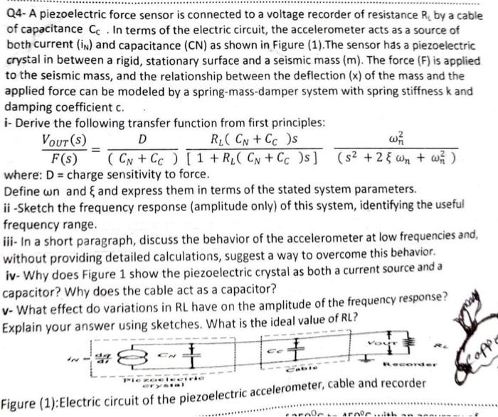
Q4- A piezoelectric force sensor is connected to a voltage recorder of resistance RL by a cable of capacitance Cc. In terms of the electric circuit, the accelerometer acts as a source of both current ( iN) and capacitance (CN) as shown in Figure (1). The sensor has a piezoelectric crystal in between a rigid, stationary surface and a seismic mass (m). The force (F) is applied to the seismic mass, and the relationship between the deflection (x) of the mass and the applied force can be modeled by a spring-mass-damper system with spring stiffness k and damping coefficient c. i- Derive the following transfer function from first principles: F(s)VOUT(s)=(CN+CC)D[1+RL(CN+CC)s]RL(CN+CC)s(s2+2n+n2)n2 where: D = charge sensitivity to force. Define w n and and express them in terms of the stated system parameters. ii -Sketch the frequency response (amplitude only) of this system, identifying the useful frequency range. iii- In a short paragraph, discuss the behavior of the accelerometer at low frequencies and, without providing detailed calculations, suggest a way to overcome this behavior. iv-Why does Figure 1 show the piezoelectric crystal as both a current source and a capacitor? Why does the cable act as a capacitor? v - What effect do variations in RL have on the amplitude of the frequency response? Explain wanur ancwar using sketrhes. What is the ideal value of RL? Figure (1): Electric circuit of the piezoelectric accer
Step by Step Solution
There are 3 Steps involved in it

Get step-by-step solutions from verified subject matter experts