

Question: An air duct system is shown in Figure-1. The air enters at point A with a static pressure of 12 mm of water. The
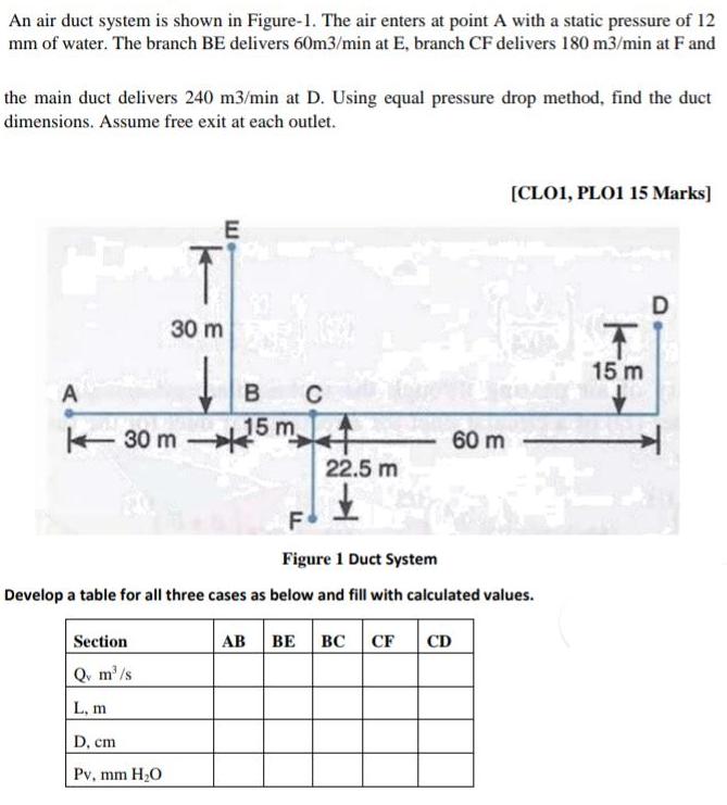
An air duct system is shown in Figure-1. The air enters at point A with a static pressure of 12 mm of water. The branch BE delivers 60m3/min at E, branch CF delivers 180 m3/min at F and the main duct delivers 240 m3/min at D. Using equal pressure drop method, find the duct dimensions. Assume free exit at each outlet. [CLO1, PLO1 15 Marks] 30 m 15 m C 15 m - 30 m 60 m 22.5 m F Figure 1 Duct System Develop a table for all three cases as below and fill with calculated values. Section AB BE CF CD Q. m'/s L, m D, cm Pv, mm H2O
Step by Step Solution
3.34 Rating (148 Votes )
There are 3 Steps involved in it
6om Iml 240mmi D 60240180m2mi F 18o mmin 240180t ... View full answer

Get step-by-step solutions from verified subject matter experts