

Question: Question 1 1. Draw a multi clock cycle pipeline diagram for the following program sub St2, Stl, St0 add St4, St2, St3 add St5, St2,
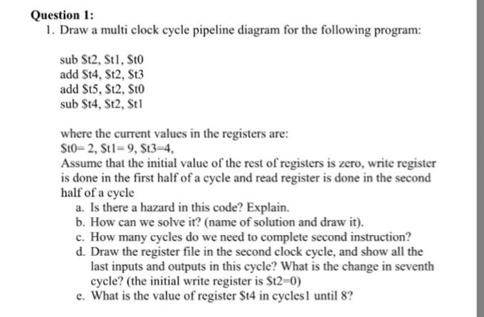
Question 1 1. Draw a multi clock cycle pipeline diagram for the following program sub St2, Stl, St0 add St4, St2, St3 add St5, St2, St0 sub St4, St2, Stl where the current values in the registers are: St0-2, St 1-9, $t3-4 Assume that the initial value of the rest of registers is zero, write register is done in the first half of a cycle and read register is done in the second half of a cycle a. Is there a hazard in this code? Explain. b. How can we solve it? (name of solution and draw it). c. How many cycles do we need to complete second instruction? d. Draw the register file in the second clock cycle, and show all the last inputs and outputs in this cycle? What is the change in seventh cycle? (the initial write register is St2-0) e. What is the value of register St4 in cyclesI until 8
Step by Step Solution
There are 3 Steps involved in it

Get step-by-step solutions from verified subject matter experts