

Question: Question 1 : External forces are applied to the system as shown in Figure 1 . Determine; ( a ) the zero force members, (
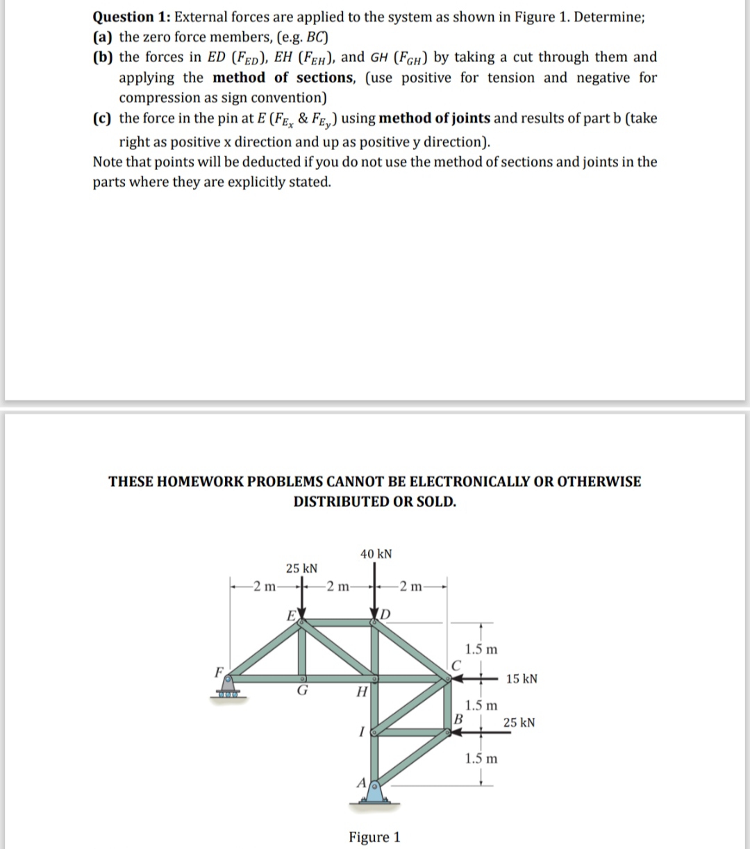
Question : External forces are applied to the system as shown in Figure Determine;
a the zero force members, eg
b the forces in and by taking a cut through them and applying the method of sections, use positive for tension and negative for compression as sign convention
c the force in the pin at & using method of joints and results of part b take right as positive x direction and up as positive y direction
Note that points will be deducted if you do not use the method of sections and joints in the parts where they are explicitly stated.
THESE HOMEWORK PROBLEMS CANNOT BE ELECTRONICALLY OR OTHERWISE DISTRIBUTED OR SOLD.
Step by Step Solution
There are 3 Steps involved in it
1 Expert Approved Answer
Step: 1 Unlock

Question Has Been Solved by an Expert!
Get step-by-step solutions from verified subject matter experts
Step: 2 Unlock
Step: 3 Unlock