

Question: Question 1 For the beam shown below, L = 9 m . ( 1 ) Analyse the beam assuming E l is constant. ( 2
Question
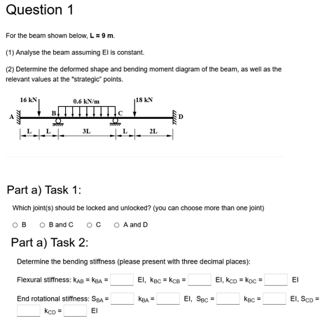
For the beam shown below,
Analyse the beam assuming is constant.
Determine the deformed shape and bending moment diagram of the beam, as well as the
relevant values at the "strategic" points.
Part a Task :
Which joints should be locked and unlocked? you can choose more than one joint
B
and
A and
Part a Task :
Determine the bending stiffness please present with three decimal places:
Flexural stiffness:
End rotational stiffness:
EI
El Part a Task :
Determine the distribution factor DFabsolute value; please present with four decimal places:
Determine the Fixed End Moment FEMkNmassuming anticlockwise positive; please
present with two decimal places:
CEM...
Fill in the table below actual values; please DO NOT present the values in traction: Part a Task :
Determine all support reactions fill in with absolute values:
Vertical reaction at :
uarr
Vertical reaction at :
Vertical reaction at :
Vertical reaction at :
What is the local maximum moment between A and absolute value
What is the local maximum moment between B and C absolute value
What is the local maximum moment between and absolute value
kNmPart c Task :
Bending force diagram of the beam:
Step by Step Solution
There are 3 Steps involved in it
1 Expert Approved Answer
Step: 1 Unlock

Question Has Been Solved by an Expert!
Get step-by-step solutions from verified subject matter experts
Step: 2 Unlock
Step: 3 Unlock