

Question: Question 1 In the structure shown P 1 = 2 8 k N , P 2 = 4 2 k N , and W =
Question
In the structure shown P and The pins at and are to be made of steel having ultimate shearing stress equal to Mpa, and Link link thickness is to be made of steel having ultimate normal stress equal to MPa. And given that factor of safety for shear stress will be and for normal stress will be Given also that the allowable bearing stress is equal to Mpa, Answer the questions in the table below: ALL PINS ARE IN DOUBLE SHEAR
Select the closest choice to your solution and ONLY TYPE THE LETTER IN THE BLANK A B C D
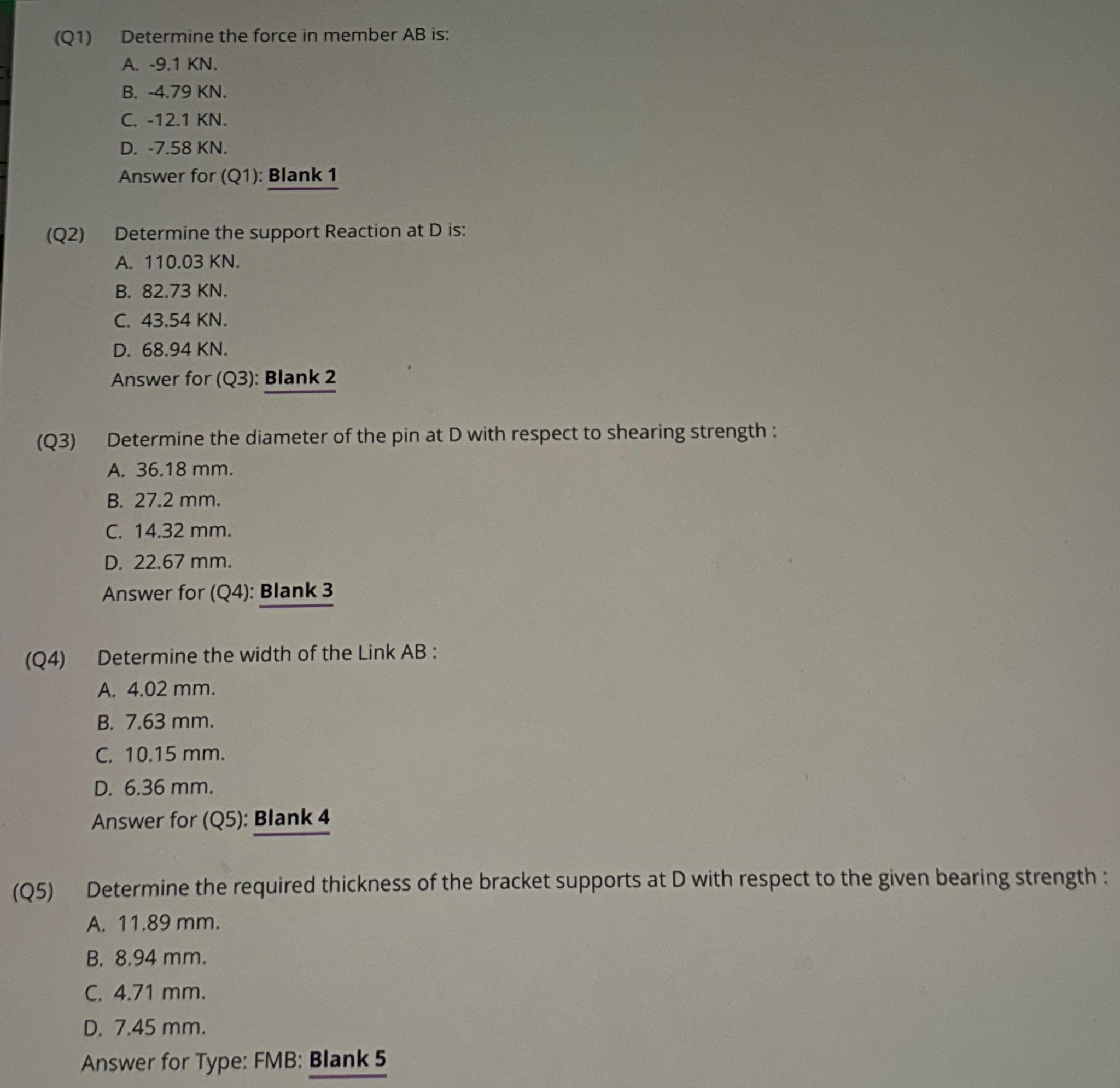
Q Determine the force in member is:
A
B
C
D
Answer for Q: Blank
Q Determine the support Reaction at is:
A
B
C
D
Answer for Q: Blank
Q Determine the diameter of the pin at D with respect to shearing strength :
A
B
C
D
Answer for Q: Blank
Q Determine the width of the Link AB :
A
B
C
D
Answer for Q: Blank
Q Determine the required thickness of the bracket supports at D with respect to the given bearing strength :
A
B
C
D
Answer for Type: FMB: Blank
Step by Step Solution
There are 3 Steps involved in it
1 Expert Approved Answer
Step: 1 Unlock

Question Has Been Solved by an Expert!
Get step-by-step solutions from verified subject matter experts
Step: 2 Unlock
Step: 3 Unlock