

Question: Question 1 . The loaded truss, shown in the figure, is supported by a roller at A and pin at B . Using the virtual
Question
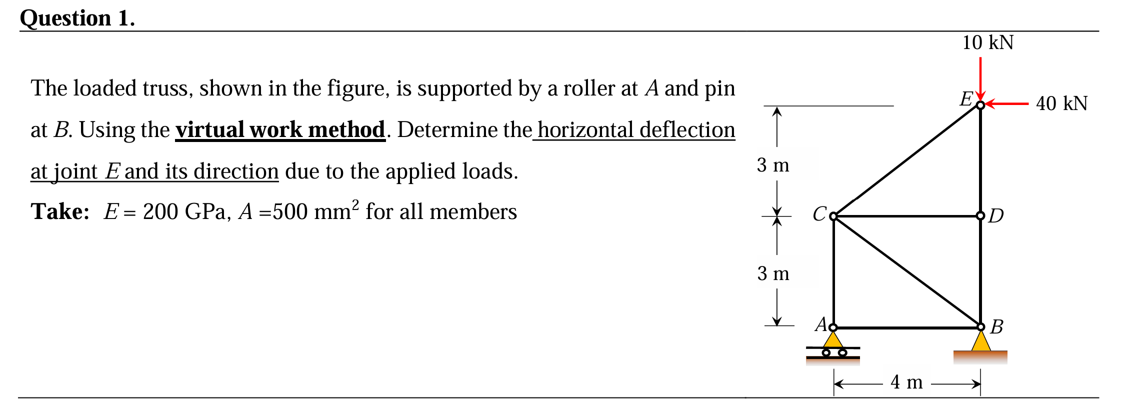
The loaded truss, shown in the figure, is supported by a roller at A and pin
at Using the virtual work method. Determine the horizontal deflection
at joint and its direction due to the applied loads.
Take: GPa, for all members
Step by Step Solution
There are 3 Steps involved in it
1 Expert Approved Answer
Step: 1 Unlock

Question Has Been Solved by an Expert!
Get step-by-step solutions from verified subject matter experts
Step: 2 Unlock
Step: 3 Unlock