

Question: QUESTION 2 ( 1 3 0 marks approx 3 0 min ) Fig. 2 shows a part of a corbel that transfers the load to
QUESTION marks approx min
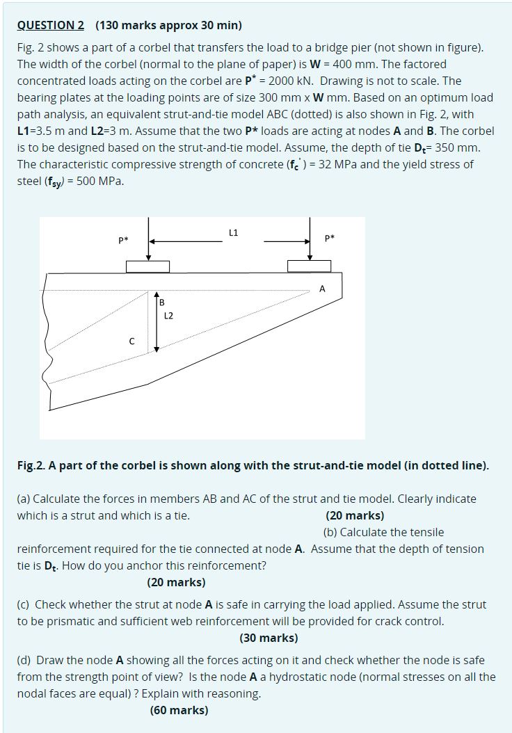
Fig. shows a part of a corbel that transfers the load to a bridge pier not shown in figure
The width of the corbel normal to the plane of paper is The factored concentrated loads acting on the corbel are Drawing is not to scale. The bearing plates at the loading points are of size Based on an optimum load path analysis, an equivalent strutandtie model ABC dotted is also shown in Fig. with
and Assume that the two loads are acting at nodes A and The corbel is to be designed based on the strutandtie model. Assume, the depth of tie
The characteristic compressive strength of concrete MPa and the yield stress of steel MPa.
a Calculate the forces in members and of the strut and tie model. Clearly indicate which is a strut and which is a tie. marks
b Calculate the tensile reinforcement required for the tie connected at node Assume that the depth of tension tie is How do you anchor this reinforcement? marks
c Check whether the strut at node is safe in carrying the load applied. Assume the strut to be prismatic and sufficient web reinforcement will be provided for crack control. marks
d Draw the node A showing all the forces acting on it and check whether the node is safe from the strength point of view?
Is the node a hydrostatic node normal stresses on all the nodal faces are equal Explain with reasoning.
Step by Step Solution
There are 3 Steps involved in it
1 Expert Approved Answer
Step: 1 Unlock

Question Has Been Solved by an Expert!
Get step-by-step solutions from verified subject matter experts
Step: 2 Unlock
Step: 3 Unlock