

Question: Question 2 2 . Consider the circuit shown in Figure 2 . 1 . In this question the circuit values referred to below are:
Question
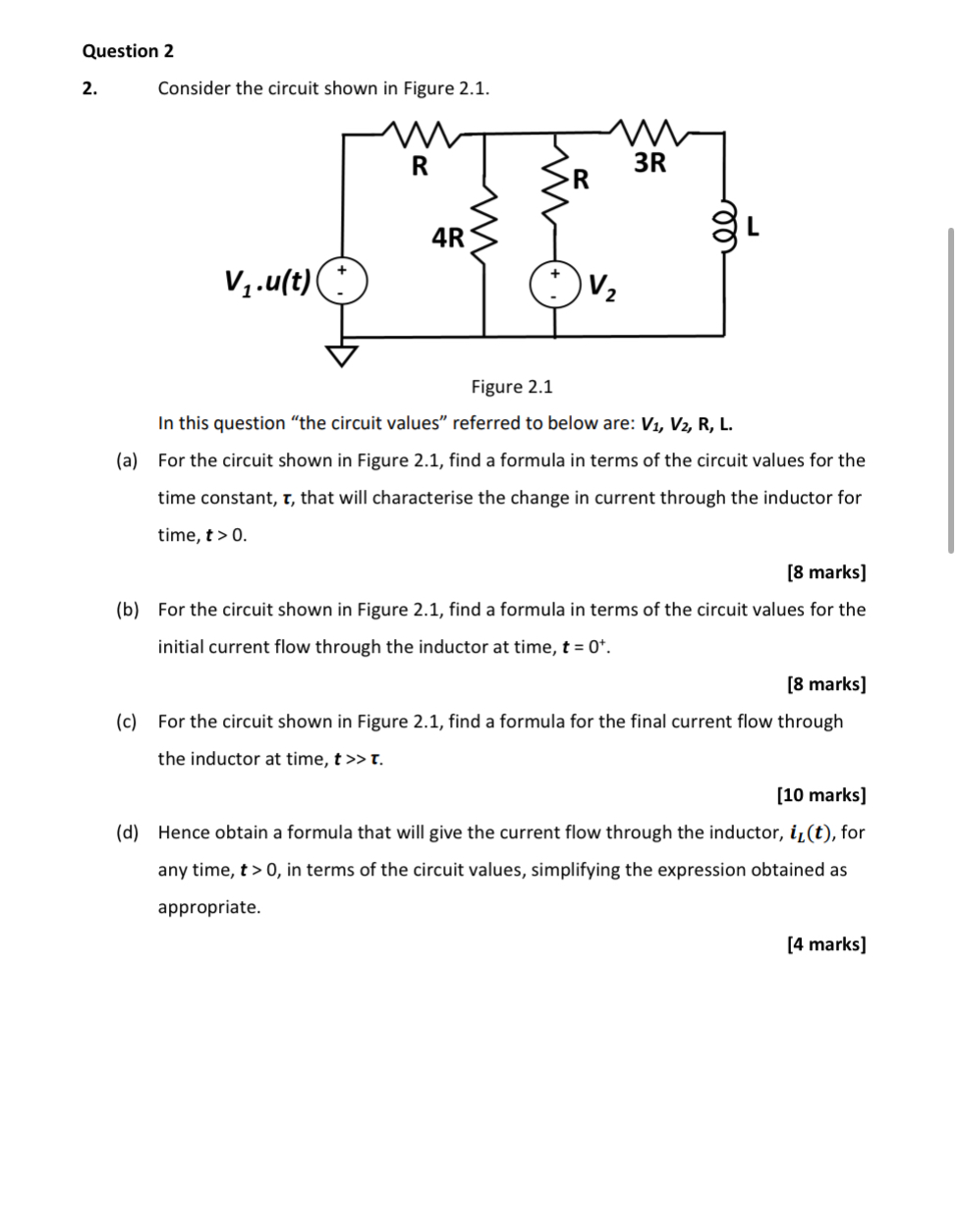
Consider the circuit shown in Figure
In this question "the circuit values" referred to below are: boldsymbolVmathbfboldsymbolVmathbfmathbfRmathbfL
a For the circuit shown in Figure find a formula in terms of the circuit values for the time constant, boldsymboltau that will characterise the change in current through the inductor for time, boldsymboltmathbf
marks
b For the circuit shown in Figure find a formula in terms of the circuit values for the initial current flow through the inductor at time, boldsymbolt
marks
c For the circuit shown in Figure find a formula for the final current flow through the inductor at time, boldsymboltgg boldsymboltau
marks
d Hence obtain a formula that will give the current flow through the inductor, boldsymboliboldsymbolLboldsymbolt for any time, boldsymbolt in terms of the circuit values, simplifying the expression obtained as appropriate.
Step by Step Solution
There are 3 Steps involved in it
1 Expert Approved Answer
Step: 1 Unlock

Question Has Been Solved by an Expert!
Get step-by-step solutions from verified subject matter experts
Step: 2 Unlock
Step: 3 Unlock