

Question: QUESTION 2 ( 5 0 % ) The truss shown in the figure is under a horizontal load at node 3 . The cross -
QUESTION
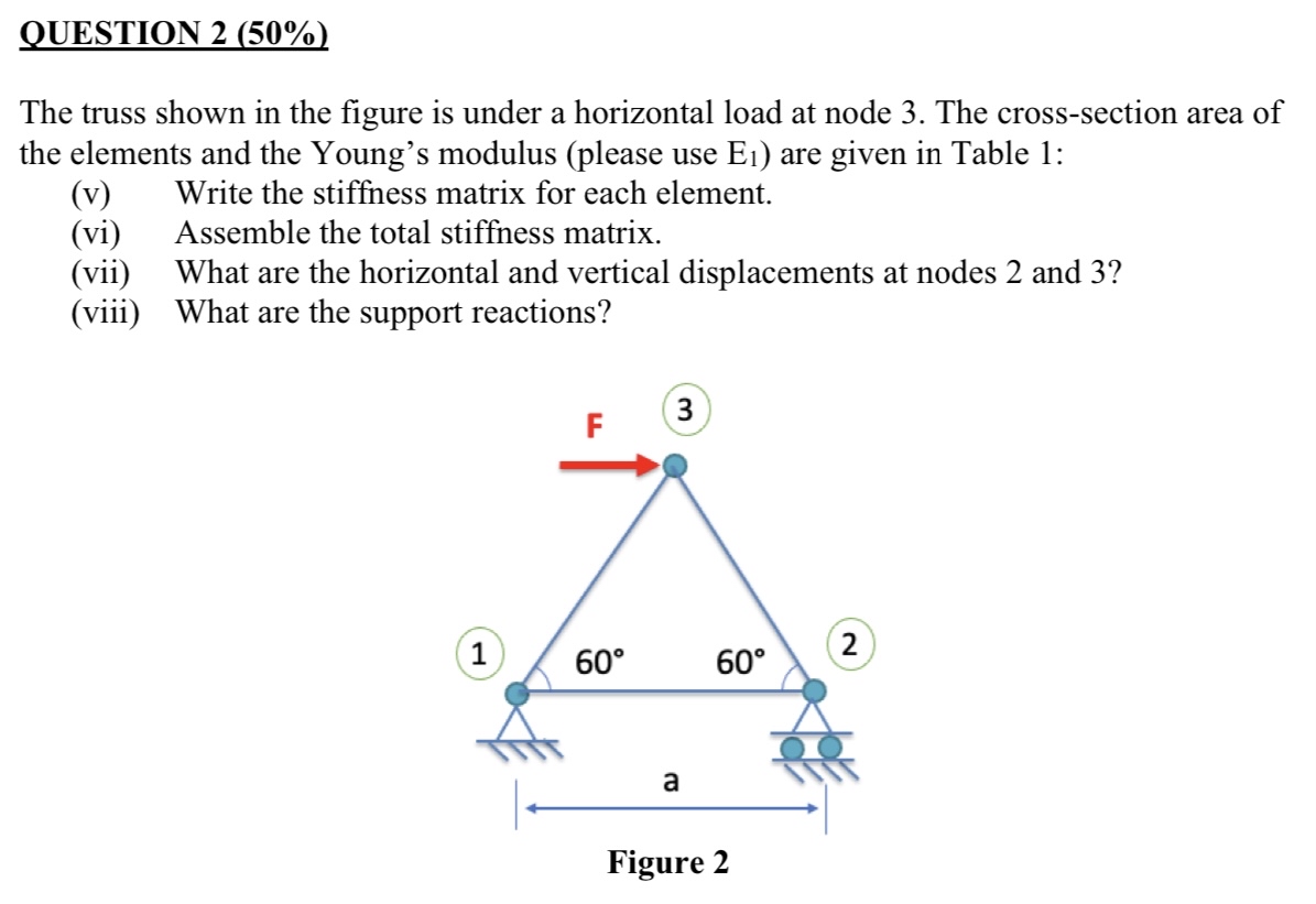
The truss shown in the figure is under a horizontal load at node The crosssection area of the elements and the Young's modulus please use are given in Table :
v Write the stiffness matrix for each element.
vi Assemble the total stiffness matrix.
vii What are the horizontal and vertical displacements at nodes and
viii What are the support reactions?
am FkN Am Ex Nm
Step by Step Solution
There are 3 Steps involved in it
1 Expert Approved Answer
Step: 1 Unlock

Question Has Been Solved by an Expert!
Get step-by-step solutions from verified subject matter experts
Step: 2 Unlock
Step: 3 Unlock