

Question: Question 2 ( a ) For the rectifier shown in Fig. 2 - 1 , determine: i . The diode conduction angle in degrees. ii
Question
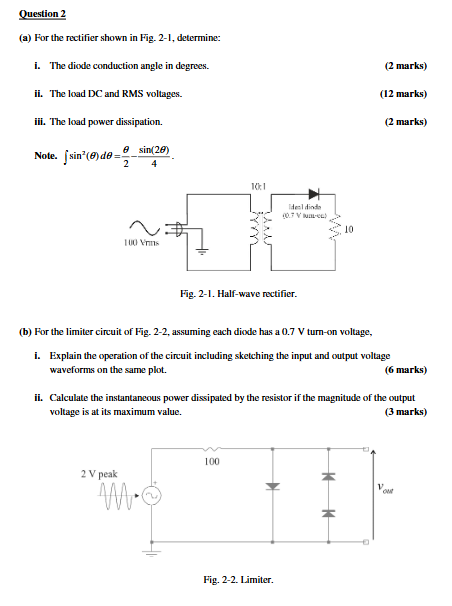
a For the rectifier shown in Fig. determine:
i The diode conduction angle in degrees.
ii The load DC and RMS voltages.
iii. The load power dissipation.
Note. int sintheta dtheta theta sintheta
b For the limiter circuit of Fig. assuming each diode has a V turnon voltage,
i Explain the operation of the circuit including sketching the input and output voltage
waveforms on the same plot.
ii Calculate the instantaneous power dissipated by the resistor if the magnitude of the output
voltage is at its maximum value.
Step by Step Solution
There are 3 Steps involved in it
1 Expert Approved Answer
Step: 1 Unlock

Question Has Been Solved by an Expert!
Get step-by-step solutions from verified subject matter experts
Step: 2 Unlock
Step: 3 Unlock