

Question: Question 2 Develop the global stiffness matrix and element forces for the beam shown in Figure 2 . The beam is in rectangle cross -
Question
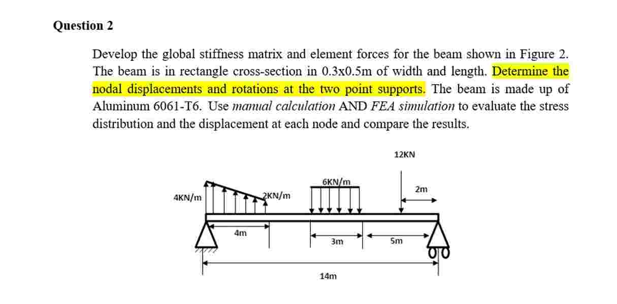
Develop the global stiffness matrix and element forces for the beam shown in Figure The beam is in rectangle crosssection in xm of width and length. Determine the nodal displacements and rotations at the two point supports. The beam is made up of Aluminum T Use manual calculation AND FEA simulation to evaluate the stress distribution and the displacement at each node and compare the results.
Step by Step Solution
There are 3 Steps involved in it
1 Expert Approved Answer
Step: 1 Unlock

Question Has Been Solved by an Expert!
Get step-by-step solutions from verified subject matter experts
Step: 2 Unlock
Step: 3 Unlock