

Question: Question 3 The continuous beam shown in Figure Q 3 is fixed at nodes 1 and 3 and has a roller at nod 2 .
Question
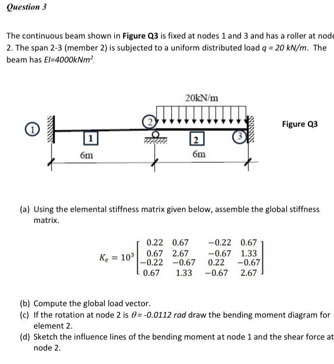
The continuous beam shown in Figure Q is fixed at nodes and and has a roller at nod The span member is subjected to a uniform distributed load The beam has
Figure Q
a Using the elemental stiffness matrix given below, assemble the global stiffness matrix.
b Compute the global load vector.
c If the rotation at node is rad draw the bending moment diagram for element
d Sketch the influence lines of the bending moment at node and the shear force at node
Step by Step Solution
There are 3 Steps involved in it
1 Expert Approved Answer
Step: 1 Unlock

Question Has Been Solved by an Expert!
Get step-by-step solutions from verified subject matter experts
Step: 2 Unlock
Step: 3 Unlock