

Question: Question 2: Figure 2 is a power diode with switched RLC circuit, Figure 3 is a power diode with switched LC Circuit and Figure 4
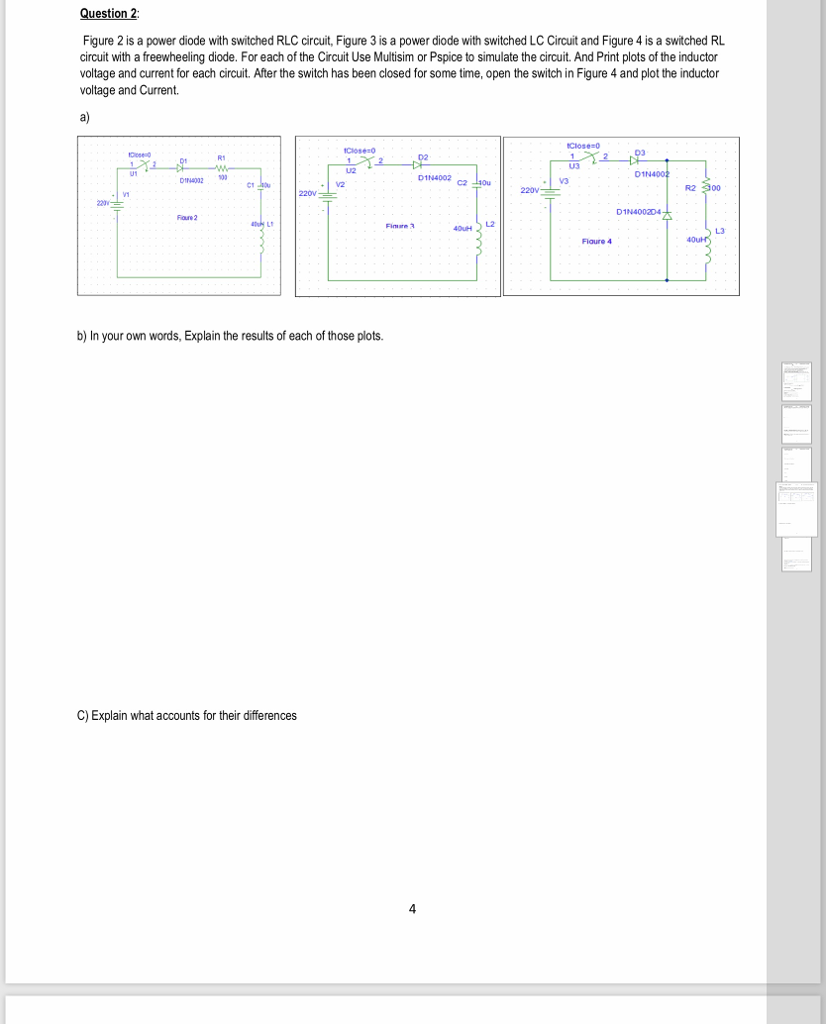
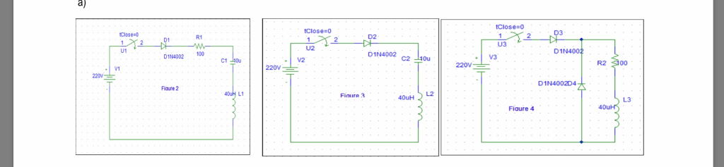
Question 2: Figure 2 is a power diode with switched RLC circuit, Figure 3 is a power diode with switched LC Circuit and Figure 4 is a switched RL circuit with a freewheeling diode. For each of the Circuit Use Multisim or Pspice to simulate the circuit. And Print plots of the inductor voltage and current for each circuit. After the switch has been closed for some time, open the switch in Figure 4 and plot the inductor voltage and Current a) 02 D1N4002 N4002 C2 V3 V2 R2 300 D1N400204 Foure 2 L2 Fimare a L3 Flaure 4 b) In your own words, Explain the results of each of those plots. C) Explain what accounts for their differences 4 Question 2: Figure 2 is a power diode with switched RLC circuit, Figure 3 is a power diode with switched LC Circuit and Figure 4 is a switched RL circuit with a freewheeling diode. For each of the Circuit Use Multisim or Pspice to simulate the circuit. And Print plots of the inductor voltage and current for each circuit. After the switch has been closed for some time, open the switch in Figure 4 and plot the inductor voltage and Current a) 02 D1N4002 N4002 C2 V3 V2 R2 300 D1N400204 Foure 2 L2 Fimare a L3 Flaure 4 b) In your own words, Explain the results of each of those plots. C) Explain what accounts for their differences 4
Step by Step Solution
There are 3 Steps involved in it

Get step-by-step solutions from verified subject matter experts