

Question: Question 2: The bracket as shown in Figure 2 is to be bolted to cast iron beams on the ceiling of a machine using
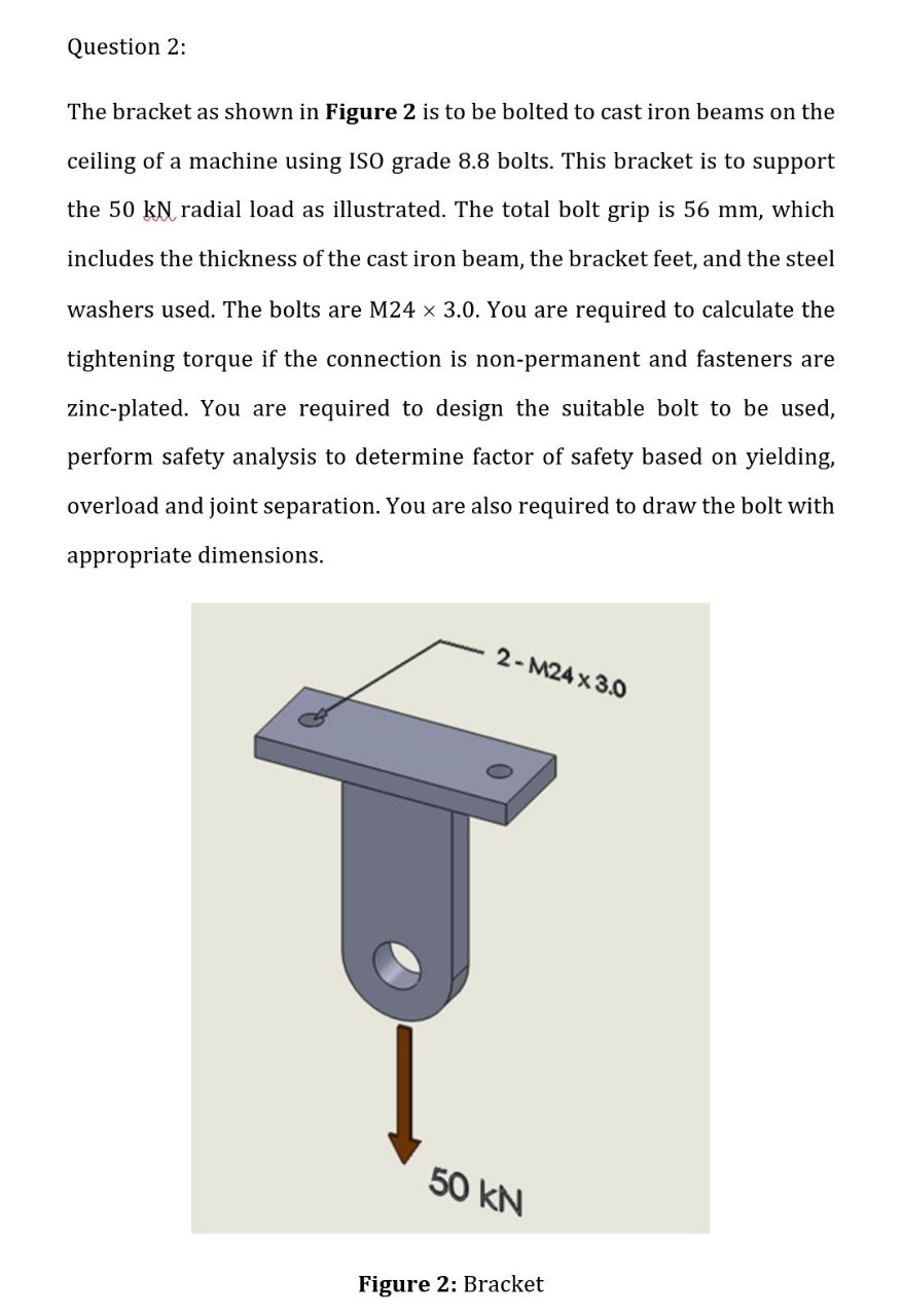
Question 2: The bracket as shown in Figure 2 is to be bolted to cast iron beams on the ceiling of a machine using ISO grade 8.8 bolts. This bracket is to support the 50 kN radial load as illustrated. The total bolt grip is 56 mm, which includes the thickness of the cast iron beam, the bracket feet, and the steel washers used. The bolts are M24 3.0. You are required to calculate the tightening torque if the connection is non-permanent and fasteners are zinc-plated. You are required to design the suitable bolt to be used, perform safety analysis to determine factor of safety based on yielding, overload and joint separation. You are also required to draw the bolt with appropriate dimensions. 2-M24 x 3.0 50 kN Figure 2: Bracket
Step by Step Solution
There are 3 Steps involved in it

Get step-by-step solutions from verified subject matter experts