

Question: Question 4 (20 pts.): The data path is given for a 4-bit multiplier. It consists of a 4-bit adder, a 4-bit register, and a 9-bit
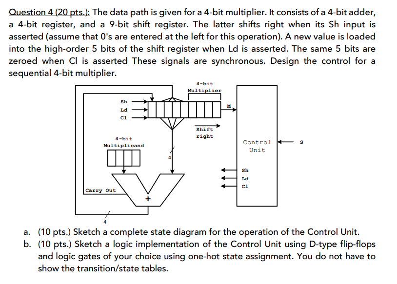
Question 4 (20 pts.): The data path is given for a 4-bit multiplier. It consists of a 4-bit adder, a 4-bit register, and a 9-bit shift register. The latter shifts right when its Sh input is asserted (assume that O's are entered at the left for this operation). A new value is loaded into the high-order 5 bits of the shift register when Ld is asserted. The same 5 bits are zeroed when Cl is asserted These signals are synchronous. Design the control for a sequential 4-bit multiplier. 4-bit Multiplier Sh Ld ci Shift right 4-bit Multiplicand S Control Unit Sh Ld ci Carry Out + a. (10 pts.) Sketch a complete state diagram for the operation of the Control Unit. b. (10 pts.) Sketch a logic implementation of the Control Unit using D-type flip-flops and logic gates of your choice using one-hot state assignment. You do not have to show the transition/state tables
Step by Step Solution
There are 3 Steps involved in it

Get step-by-step solutions from verified subject matter experts