

Question: Question 4 ( 3 4 Marks ) Figure 3 below shows the plan view of a floor structure in an office building, formed using timber
Question Marks
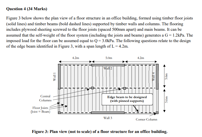
Figure below shows the plan view of a floor structure in an office building, formed using timber floor joists solid lines and timber beams bold dashed lines supported by timber walls and columns. The flooring includes plywood sheeting screwed to the floor joists spaced mm apart and main beams. It can be assumed that the selfweight of the floor system including the joists and beams generates a kPa. The imposed load for the floor can be assumed equal to kPa. The following questions relate to the design of the edge beam identified in Figure with a span length of
Figure : Plan view not to scale of a floor structure for an office building.
a What is the maximum design bending moment demand, M for the edge beam associated with the
two ULS load combinations G Q and G Present calculations to support your answer.
marks
b What is the maximum axial force demand, N for the corner column supporting the edge beam, for
the two ULS load combinations G Q and G Present calculations to support your answer
marks
c If the edge beam in Figure is to be realised with pairs of grade SG solid timber beams, each
having sections of mm xmm dry section dimensions each mm deep x mm wide
present calculations to check whether the edge beam is strong enough to resist a peak moment
demand, due to G Q of MkNm
marks
d If the edge beam in Figure is to be realised with pairs of grade SG solid timber beams, each
having sections of mm xmm ie each mm deep x mm wide present calculations to
check whether the beam is strong enough to resist a peak shear force demand, of VkN
marks
e Present checks to show whether the proposed beam section described above is stiff enough to
satisfy a displacement limit of L for the SLS load combination: G lQ
Step by Step Solution
There are 3 Steps involved in it
1 Expert Approved Answer
Step: 1 Unlock

Question Has Been Solved by an Expert!
Get step-by-step solutions from verified subject matter experts
Step: 2 Unlock
Step: 3 Unlock