

Question: Question 4 (a) Draw and write the truth-table for RS latch NOR version. Why is the condition RS = 11 not allowed? (b) Figure
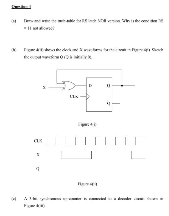
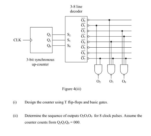
Question 4 (a) Draw and write the truth-table for RS latch NOR version. Why is the condition RS = 11 not allowed? (b) Figure 4(ii) shows the clock and X waveforms for the circuit in Figure 4(i). Sketch the output waveform Q (Q is initially 0). D CLK Figure 4(i) CLK Figure 4(ii) A 3-bit synchronous up-counter is connected to a decoder circuit shown in Figure 4(iii). (c) 3-8 line decoder O, b O, b CLK Qi Qo 3-bit synchronous O, - up-counter Og Figure 4(i) (i) Design the counter using T flip-flops and basic gates. (ii) Determine the sequence of outputs O:0,0, for 8 clock pulses. Assume the counter counts from Q:Q:Q0 = 000. 1815 l8 l l l I8 15
Step by Step Solution
3.47 Rating (157 Votes )
There are 3 Steps involved in it

Get step-by-step solutions from verified subject matter experts