

Question: QUESTION 4 (a) Figure 4 (i) shows the logic symbol and function table of a 2-to-1 multiplexer. So F 0 le So Logic symbol
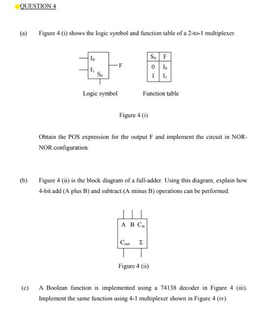
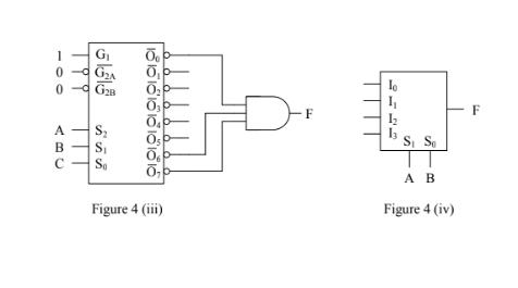
QUESTION 4 (a) Figure 4 (i) shows the logic symbol and function table of a 2-to-1 multiplexer. So F 0 le So Logic symbol Function table Figure 4 (i) Obtain the POS expression for the output F and implement the circuit in NOR- NOR configuration. (b) Figure 4 (i) is the block diagram of a full-adder. Using this diagram, explain how 4-bit add (A plus B) and subtract (A minus B) operations can be performed. . Cout Figure 4 (i) (c) A Boolean function is implemented using a 74138 decoder in Figure 4 (iii). Implement the same function using 4-1 multiplexer shown in Figure 4 (iv). F S, S A B Figure 4 (iii) Figure 4 (iv) TT
Step by Step Solution
3.45 Rating (165 Votes )
There are 3 Steps involved in it

Get step-by-step solutions from verified subject matter experts